


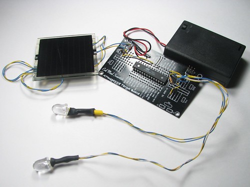
Simple Solar Circuits:
How to get started adding solar power to your small electronics projects. Use the sun to power small solar and battery powered night lights, garden lights, and decorations for halloween.
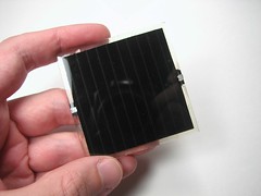
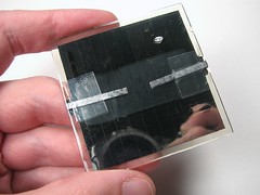
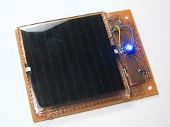
The first part of a solar circuit is… a device for collecting sunlight. To keep things simple, we’re using a single nicely made small solar panel for all of these circuits. The panel that we’re using for these circuits is this one, part number PWR1241 from BG Micro, about $3 each. This is a monolithic copper indium diselenide solar panel, apparently printed on a 60mm square of glass and epoxy coated for toughness. On the back of the panel are two (thin) solderable terminals, with marked polarity. (While you can solder directly to the terminals, be sure to stress-relieve the connections, e.g., with a blob of epoxy over your wires.) In full sunlight the panel is specified to produce 4.5 V at up to 90 mA, although 50 mA seems like a more typical figure.
[Before we move onto our first examples, a word of caution: These are small simple circuits. In building these, we will quite intentionally gloss over a number of minor details and issues that are unimportant at these low powers, but could become critical if you were to try to scale up.]
Direct Drive:
The most obvious way to use power from a solar panel is to connect your load directly to the output leads of the solar panel.
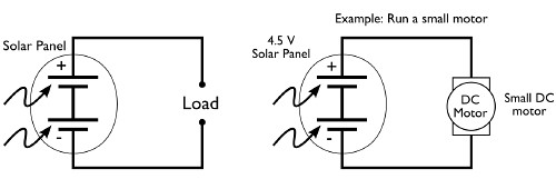
Here are a couple of examples of this in practice:

On the left, we’ve hooked up one of our little solar panels directly to a small motor taken from an old CD player. When you set it out in the sunlight or bring it close to a lamp, the motor starts to spin. On the right we’ve hooked one of the panels right up to a high-power blue LED. The reason that we’ve used a high-power LED here is that it can easily withstand 50-90 mA from the solar panel– a “regular” LED designed for 20 mA would be destroyed by that current. (The LED is the same type that we used for our high-power LED blinking circuit.)
Interruption-resistant direct drive:
The “direct drive” circuits work well for their design function, but are rather basic. They provide no energy storage, and so are quite vulnerable to blinking out when a bird or cloud passes overhead. For some applications, like running a small fan or pump, that may be perfectly acceptable. For other cases, like powering a microcontroller or other computer, a brief power interruption can be disruptive. Our next circuit design adds a supercapacitor as a “flywheel” to provide continued power during brief interruptions.
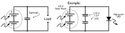
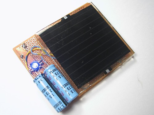
Instead of adding a single supercapacitor, you might notice that we’ve actually added two. That’s because the supercaps that we had on hand are rated for 2.75 V– not enough to handle the 4.5 V output of the panel when sunlight is present. To get around this limitation, we used two of the caps in series, for which the voltage ratings add, giving us a barely-okay total rating of 5.5 V. (Note: be careful adding capacitors of different values in series– the voltage ratings may scale in non-obvious ways.) When first exposed to the light, this circuit takes about 30 s to 1 minute to charge the capacitors enough that the LED can turn on. After it’s fully charged, the circuit can be removed from the sunlight and still drive the blue LED for about 30 s to 1 minute– a very effective flywheel for light duty applications.
Adding a battery
While interruption resistance is nice, a capacitor generally does not provide sufficient energy storage to power a solar circuit for extended periods of time in the dark. A rechargeable battery can of course provide that function, and also provides a fairly consistent output voltage that a capacitor cannot. In this next circuit, we use the solar panel to charge up a NiMH rechargeable battery and also LED off of the power, which will stay on when it gets dark out.
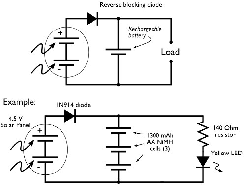

In this circuit the solar panel charges up a 3-cell NiMH battery (3.6 V). Between the two is a “reverse blocking” diode. This one-way valve allows current to flow from the solar panel to the battery, but does not allow current to flow backwards out of the battery through the solar panel. That’s actually an important concern because small solar panels like these can leak up to 50 mA in the reverse direction in the dark. We’re using a garden-variety 1N914 diode for reverse blocking, but there are also higher-performance diodes available that have a lower “forward voltage.”
In this design we are continuously “trickle charging” up the battery when sunlight is present. For NiMH batteries and sealed lead-acid batteries (the two types that are most suitable for this sort of un-monitored circuit) it is generally safe to “trickle” charge them by feeding them current at a rate below something called “C/10”. For our 1300 mAh battery cells, C/10 is 130 mA, so we should keep our charging below 130 mA; not a problem since our solar panels only source up to 90 mA.
The other thing to notice about this circuit is that it’s pretty darned inefficient. The LED is on all the time, whenever the battery is at least slightly charged up. That means that even while the circuit is in bright sunlight it is wasting energy by running the LED: a sizable portion of the solar panel current goes to driving the LED, not to charging the battery.
Detecting Darkness
We have written recently about how to make a useful dark-detecting LED driver circuit. That circuit used an infrared phototransistor. To add a darkness detecting capability to our solar circuit is even easier, actually, because our solar panel can directly serve as a sensor to tell when it’s dark outside.
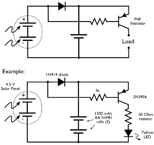
To perform the switching, we use a PNP transistor that is controlled by the voltage output from the solar panel. When it’s sunny, the output of the panel is high, which turns off the transistor, but when it gets dark, the transistor lets current flow to our yellow LED. This circuit works very well and is a joy to use– it would make a good upgrade to the dark detecting pumpkin to make it go solar with this circuit.
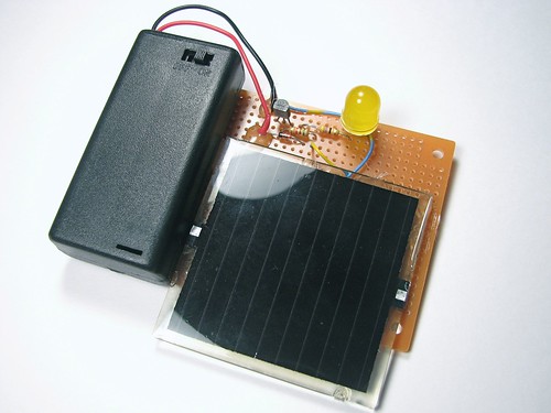
A solar garden light circuit
While the last circuit works well for driving a yellow or red LED, it runs at 2.4 V (the output of the NiMH battery), it does not have sufficient voltage to drive a blue or white output LED. So, we can add to that circuit the simple Joule Thief voltage booster to get a good design for a solar garden light: A solar-charged battery with a dark detector that drives a Joule Thief to run a white output LED.

Naturally, you’d want to give this a tough, weatherproof enclosure if it were going to be run outside. (A mason jar comes to mind!) This circuit is actually very close to how many solar garden lights work, although there are many different circuits that they use.
Adding a microcontroller
Our last circuit examples extend the previous designs by adding a small AVR microcontroller. We use the voltage output from the solar panel again to perform darkness detection, but instead take it to an analog input of the microcontroller. The microcontroller is potentially a very low current, efficient device that lets you save power by not running the LED all the time, but (for example) waiting until an hour or two after darkness and/or fading the LEDs on or off, or even intermittently blinking for very low average power consumption.
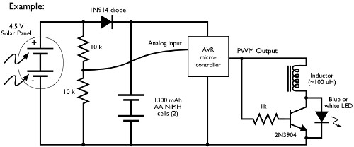

In this example we have the PWM (pulse-width modulation) output of the microcontroller driving a Joule Thief style voltage booster to run the white LED. (This is one of many, many different working designs for this sort of boosting circuits.)
We also made a second version of this circuit, with two red LED outputs to make a spooky Jack-o’-lantern:
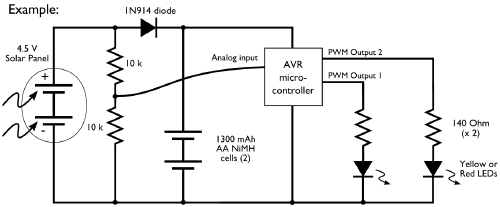

To finish it up, we carved a beautiful white pumpkin and added this circuit to make our microcontroller-driven, dark-detecting, solar-powered programmable pumpkin, which faded its eyes in and out one at a time. Note the long leads on the solar panel and wires to the LEDs to reach.
We hope that you might find this introduction to simple solar circuits helpful; let’s see those solar jack-o-lanterns!
You can find more pumpkin projects in our Halloween Project Archive.

Hey,
I enjoyed it very much.
Because of that, I would like to make a batteries charger circuit with solar power.
But I have some questions:
-Did I need to include some resistor in the circuit?
-Will there a problem when the batteries get full-charged and the solar panel still receiving the sunlight even I put a diode?
Thank you very much.
Keep the good work!
Im going to make the circuit with the compacitors but im just wondering where did u get the capicitors and is there another solution instead of soldering?
Supercapacitors like these can be purchased at many electronics stores, especially online. Avoid the "memory backup" types; they do not have a high current rating.
You *can* do this without soldering, using crimp connectors or just twisting the leads, but your results may be less than reliable.
—
Windell H. Oskay
drwho(at)evilmadscientist.com
http://www.evilmadscientist.com/
There’s always keeping your eyes out for good deals on those solar yard stake lights, then hacking in some AVR. I’ve found some deals that end up being cheaper than you can buy the bits seperatly.
Good luck, its not much power.
This is cewl!!!!!!! just asking, do you think this could be modified to power a parallax BOE-bot? If so how big would the panels need 2 be??
I don’t know how much current the BOE-bot requires, but it might need a pretty good sized panel.
—
Windell H. Oskay
drwho(at)evilmadscientist.com
http://www.evilmadscientist.com/
it requires min-5V of power, but is designed to run on 5V-9V i use rechargable batteries 4 mine so it would be fine for that, but, while I am ok in programming, I have no experience in the actual construction of the circuts so i hav know idea of how to do this without frying my Stamp.
If you really have "no idea" how to do it then you might want to hold off a bit on this project– when messing with the power supply you should at least have a pretty good idea what you’re doing, or you’re quite likely to make an expensive mistake.
—
Windell H. Oskay
drwho(at)evilmadscientist.com
http://www.evilmadscientist.com/
The input on the BOE-bot has a built-in 7805 (or is it something else?) regulator, so as long as you stay above ~6 volts and provide enough current, it would work.
Great writeup. I’d recently mailed you guys about this exact question, and it’s fantastic to see this info posted!
I had a bit of trouble building the "A solar garden light circuit" piece. I eventually ended up replacing the 5k resistor with an 150ohm resistor, which fixed it. I built it on a breadboard, and I’m not quite sure what I did wrong. With anything higher than that, the LED would never get enough juice to light up.
Any ideas?
Sounds like your Joule Thief circuit isn’t working– either that, or you’ve mis-wired your PNP transistor.
—
Windell H. Oskay
drwho(at)evilmadscientist.com
http://www.evilmadscientist.com/
I believe you’re right. I’m going to keep working with it. It’s such a simple circuit, I can’t imagine what I did wrong :(
Thanks!
amazing!
Hi Windell,
Woo-hoo…. Long term fan, First post….
You say: "….In building these, we will quite intentionally gloss over a number of minor details and issues that are unimportant at these low powers, but could become critical if you were to try to scale up."
Can you point me in the right direction to find more information about controlling higher powered panels? I’ve just ordered my first Arduino, and I’ve got some serious playing to do.
Thanks
There really are a *lot* of details to worry about as you scale up. Some are pretty straightforward– like you can’t use the diode that we do because it’s not rated for that much current, but less straightforward is that you want to replace it with a diode that has a lower forward voltage.
Also, for combining multiple panels you need to worry about what happens when there is mismatch from the output of different panels– like when a shadow falls over part of the panel, so all of your cells and panels need to be combined with the proper blocking and bypass diodes to prevent reverse current from flowing through not just whole sets in series, but also through individual cells.
There’s also a lot to worry about in making sure that you treat your batteries well. For low-power trickle like in our systems, there’s not much to worry about. But for larger systems, you *really* need to know what you’re doing.
Generally speaking, if you want to set up a solar power system, you need to start approaching it from the perspective of someone doing so– scaling up from our little circuits can lead to big trouble unless you also understand what issues come up in large systems. Start out by using Google– look for information about how to hook solar panels together, for information on basics of solar energy, and solar circuits, on batteries for solar systems, and so forth. There is a *lot* of information out there.
A separate issue is how to use (for example) the microcontroller to control things with higher power– that’s a matter of learning about solid state and mechanical relays, mostly.
—
Windell H. Oskay
drwho(at)evilmadscientist.com
http://www.evilmadscientist.com/
some say to put the joule thief to work charging the batteries, making the panel into joule thief driver:
http://www.talkingelectronics.com/projects/SolarCharger/SolarCharger.html
am curious what you think the efficiency difference is between:
– DC charging the batteries/ RF LED driver
– RF charging the batteries/ DC LED driver
bye!
http://www.ciat-lonbarde.net
410 362 8364
I am still a kid and I am not allowed to solder alone and I don’t have soldering gun. Are there any options to soldering? Also, how much would all these parts cost?
thanks
First off, you *do not* want to solder alone, even when you’re not just a kid. It’s basic safety practice. Also, you want a soldering iron, not a gun. The "gun" types are suitable for plumbing and big things, but not really for small scale electronics. When doing wiring, many connections can be made by using crimp connectors rather than soldering. However, when working on a circuit board, there’s not much that can substitute for actually soldering.
The parts that we’ve used here are all relatively inexpensive; the solar panels are about $3 each. The most expensive thing that we used is the microcontroller, which costs about $5.
—
Windell H. Oskay
drwho(at)evilmadscientist.com
http://www.evilmadscientist.com/
I know very little in the field electronics, i have interest in learning how to build this simple solar circuit. i am a new member. i would be grateful if details could be sent to my e-mail.
I really enjoyed the project so far. but i would like to design a solar circuit to power up to 20 white led bulb at a time, then how do i get the materials can i buy them from you, how much does it cost and how do i pay or get them. Also to design for a 6V rechargeable battery. Thanks, you can kindly reply to my mail box now.
You’re on your own; we don’t make or sell anything like that.
—
Windell H. Oskay
drwho(at)evilmadscientist.com
http://www.evilmadscientist.com/
interesting article! here is another way to use solar power:
http://www.solarbotics.net/library/circuits/se_t1_mse.html
Ok I have built a couple now and I wanted to know if there are small bifilar toroids I can purchase? My homemade ones are huge.
Yes; there are even small surface mount ones that you can get.
—
Windell H. Oskay
drwho(at)evilmadscientist.com
http://www.evilmadscientist.com/
Do you have any part numbers? Also my led comes on to early before the sun is even down. Can I lower the 5k resister to make it less sensitive?
This was a fantastic article.
But could you please explain in detail why you specifically chose a 5k (as opposed to a 100ohm or 100K) resistor? I understand basic V=IR, and I have the data sheet for the 3906PNP. Im sure the resistor has something to do with the solar panel putting out 4.5@90mA, but I would love to see how you worked the numbers to come up with the need for a 5K resistor. thanks.
The base current of the transistor needs to be high enough to turn the LED on through the (rather low) transistor gain, but also as low as possible so as to not waste electricity unnecessarily.
—
Windell H. Oskay
drwho(at)evilmadscientist.com
http://www.evilmadscientist.com/
Hello Evil Mad Scientists!
Thank you for this inspiring article on stuff I’ve been wanting to do with my defunct garden lights. If I can get the joule thief approach to power my high-power LEDs, I should be able to get even brighter versions.
But the main thing I wanted to ask: If I wanted to make a solar powered battery charger, well, obviously you have shown me how. But I’d like to be able to see if the battery is fully (or close to fully) charged. Is there a simple way to do that?
Thanks in advance,
-Lars
The obvious way is still the best: disconnect from the charging source and measure with a voltmeter.
This could be as simple as a momentary switch that disconnects one and connects the other, and the "voltmeter" could be made of one or more LEDs, possibly in series with one or more "plain" diodes to create the voltage threshold that you want to detect. There are also some nice low-power "voltage detector" chips out there that can light an LED when any specific threshold is reached.
—
Windell H. Oskay
drwho(at)evilmadscientist.com
http://www.evilmadscientist.com/
Hi,
Thanks for a wonderfully clear description!
I was wondering, in a setup like the above with a solar panel/battery/atmega that makes the leds blink only when its dark, how would you be able to calculate how long it will run before the battery runs out, given that there is enough sun to have the battery completely full by the time the darkness activates the system?
Many thanks!
That’s pretty straightforward. You would need to know the capacity the battery cells (usually written on them in mAh), the average current that the microcontroller takes (which can be found in the datasheet, given its power input and clock speed, and noting that the ADC is active) and guessing 40 mA or so for the LED driver part when it’s turned on. Better would be to just *measure* the average current consumption with a multimeter.
—
Windell H. Oskay
drwho(at)evilmadscientist.com
http://www.evilmadscientist.com/
Hi and thank you EMSL!
These are enormously helpful explanations of these circuits!
I’m working on a permanent light graffiti project which is basically a combination of the classic LED throwie with LED electronic graffiti. My main concern is how to keep the battery in top condition to keep the circuit (and art) as near to permanent as possible. I know that for large voltage solar circuits the battery has to be kept from over charging and that for smaller ones the trickle charge is ok. Will adding some kind of voltage regulator circuit to a 9v recharging battery noticeably prolong the life of my light art or is it an overcompensation?
Thanks again, keep up the learning and sharing!
Hi,
In the version with a micro controller, I was wondering where you mention ‘waiting until an hour or two after darkness’, what would you reckon to be the least power consuming way of making the controller wait for one or two hours? Is it just something like delay(600000) or is there a more effective way?
Also, what does the line between the two 10k resistors and the Analog In tell the controller? Is it a voltage level that needs to reach a certain height (or low-th) that you would then use as a trigger in the script?
Thanks!
>where you mention ‘waiting until an hour or two after darkness’,
>what would you reckon to be the least power consuming way of
> making the controller wait for one or two hours?
>Is it just something like delay(600000) or is there a more effective way?
Depends on the specific microcontroller and how you have it configured. On the ATmega48/168 that we used in this project, you could run off of the internal clock at 500 kHz, which makes the active-state current consumption about 0.2 mA when running at 2.4 V. (As opposed to about 2 mA when running at 8 MHz). You can also run at lower frequency for lower-yet power consumption.
If you’re just sitting idle, you can use a hardware timer with a wake-up interrupt and put the AVR into idle mode. That turns off the AVR core, but lets the timer keep running. Idle-mode power consumption is only 0.03 mA at 500 kHz. You could wake up whenever the timer runs out, and check to see if enough idle periods have elapsed, or go back to idle if it’s still within the 2-hour window.
>Also, what does the line between the two 10k resistors and the Analog In
> tell the controller? Is it a voltage level that needs to reach a certain height
> (or low-th) that you would then use as a trigger in the script?
It just lets you measure the input voltage– you don’t want to use that input without a voltage divider, because the analog inputs aren’t designed to accept voltages that are larger than the power supply voltage.
—
Windell H. Oskay
drwho(at)evilmadscientist.com
http://www.evilmadscientist.com/
Hello,
I was wondering, what does the inductor do in the version with a micro controller, just because mine works both with and without the inductor? Does it have to do with a lower power consumption?
Thanks!
The inductor is there to give a voltage boost in cases where the LED forward voltage is high (e.g., 3 -4 V) but the voltage supplied to the microcontroller is only about 2 – 2.5 V. If you’re using a red LED, for example, you’ll never need the inductor. Or if your battery voltage is higher….
—
Windell H. Oskay
drwho(at)evilmadscientist.com
http://www.evilmadscientist.com/
Thank u Mr.E.M.scientist 4 such great stuff.
But can u tell me some tricks to increase current o/p in order to drive a small DC motor up to 100 to 500 mA,
I think a 9.V panel to power the 6V (5.C) rechargeable batteries, I’m about to do (try) it.
[link:]http://forums.trossenrobotics.com/blog.php?u=3873
Wendell – do you have any part numbers (or the inductance and current ratings) for SMD versions of the bifial Toroids?
I want to modify my store bought solar garden lights into pummers and need a joule thief circuit to make it work I believe. I’m new to electronics and don’t know what to look for at digikey or mouser.
Thanks!
That’s *Windell* please.
68 uH, 350 mA or so. Bourns type PM3602-68-B-RC. Digi-key P/N M8670-ND or M10142CT-ND, which appears to be an exact substitute. Wire two opposite terminals of the device together for use with a Joule Thief.
Windell H. Oskay
drwho(at)evilmadscientist.com
http://www.evilmadscientist.com/
*cough* *cough*
My apologies Windell!
Many thanks!
—
T
It seems that in the solar garden light circuit, two cells are necessary to get the PNP ttransistor to conduct and turn off when the solar cell is getting light. Is there any way to get this to work with only one 1.2v NiMh cell or am I doing something wrong?
When the solar cell is receiving light, it biases the base at 4.5 V and the emitter at about 4.0 V. That’s about as clamped off as you can be. The battery doesn’t have much say in the matter.
Windell H. Oskay
drwho(at)evilmadscientist.com
http://www.evilmadscientist.com/
Thanks, but still having the same issue. If I were to remove the input from the solar panel throught the 5K resistor, the thief should turn on and light, coorrect?
With only one battery this does not work, with two batteries (2.4V) it works for some reason. Any idea what may be wrong?
Could I possibly need more windings on the torroid?
Your input is much appreciated, thanks–
Hello!
I have exacly opposite preoblem, it works only with one battery (1.2V).
Thanks for answer.
This is an excellent introduction to solar circuits. Thanks for writing it :)
Thank you for a very informative and useful article. One writer mentioned a use for defunct solar garden lights: that’s exactly what i have been doing, by taking them apart and incorporating the bits into old hurricane lanterns. I found NiCad cells almost unobtainable as replacements and am using NiMh. The bottom of the lantern tank must be cut away. The solar panel is removed from the old garden light, solder long wires onto it and feed them down one of the main metal struts that support the top so they extend down to the now open base. The solar panel is glued to the top of the lantern. The LED is unsoldered and its wires extended so that it can sit just above where the wick would extend. The wires from the solar panel and LED are then resoldered and the innards of the old garden light, including battery are glued into the base of the lantern. We use it as a night light in the hallway, taking it outside to charge daytime. I would like to do similar refurbs of old hurricane lanterns but increase the powe r of the LED to make it more useful as a regular lantern.
how can i add dark activatec switch on this circuit with
thats cool.
i exactly got the info i was searching for my project.
thank you.
It appears as though your entire article has been ripped off without credit:
http://www.solarpowerwindenergy.org/2009/04/26/how-to-build-a-small-solar-circuit-wiring-diagrams/
@#$%^&*!!!
Windell H. Oskay
drwho(at)evilmadscientist.com
http://www.evilmadscientist.com/
Wow, doesn’t anyone know who the #&!% to cite their sources anymore?
Sorry for you Wendel, but (don’t take this the wrong way) EMSL seems to have a problem with people ripping off your ideas/projects without giving credit… You guys might wanna consider getting a Lawyer.
Tried this circuit, but one battery stops charging after a couple of weeks, is there a specific size battery required for the circuit to work. The supply voltage is 4.5 volts.
On the simple dark detecting circuit.
I know that its more than possible to run the thing using a single 1.2 volt NiMH using a Joule Thief.
My question is this: If I only use a single 1.2 volt battery, will I run into any problems charging it off the 4.5 volt solar panel? AKA will I fry the battery?
You will not have a problem overcharging the batteries. Most batteries trickle charge is much larger than what a small solar panel can provide.
I replicated the darkness-detecting circuit to drive a motor, but I had to put a resistor between the transistor base and the negative terminal of the solar panel to get it to work. Thoughts? (I am using a 2N2907 transistor, but I don’t think that matters.)
I’m only getting about 1mA out of the 3906 transistor. After some testing, it seems that the 3906 needs more current to its base to reach full saturation (at which point the current raises considerably). The solar panel I’m using has next to no current through it when it’s dark. (I’m using a flexible solar cell) While 1mA is enough to dimly light a yellow LED. It’s not enough to drive a the step up circuit I have. Is this expected behavior given the panel I’m using? -Thanks
These circuits all use high-performance solar cells. The flexible cells that I have used are on the opposite end of the spectrum– very low performance. Don’t expect much output.
Windell H. Oskay
drwho(at)evilmadscientist.com
http://www.evilmadscientist.com/
I’m using a soalr garden light in a school assignment to power a fan, as far as i can tell the LDR is intergrated into the solar panel and i am wondering how to reverse the curcuit to make it run during the day, any simple way of changing this? removing a transistor..e.g
any help appreciated.
HI
If I use a 6.8V 90mA solar panel and high power leds which are 1w 3.2v with doubling the battery pack, will the circuit still be able to function?
Regards
Hi all.
Got a question. We entered a solar boat race last year and didi OK, but lost the final due to cloud cover. We were running 4 x 1.2v panels in series to power the 2.4v motor. The whole boat weighed about 900g. It ran great in 75% + sun (motor was quite cool after the 3 minute race), but stalled out under heavy cloud. Any recommendations for a better set up. No fancy stuff is allowed ……. I was thinking 4 x 4.8 / 5.5 v panels in parallel. Any advice would be much appreciated
Are you allowed batteries? If so these can be used as a "buffer".
If not then you might like to try this simple circuit that can boost PV panel output: http://www.voltscommissar.net/minimax/minimax.htm#option1
-experiment with setup, maybe two panels in series might work well. It will overload the motor but pushing them to the limits is what F1 racing is all about! :o)
Do you have sample code for the solar-powered programmable jack o lantern?
I’m pretty new to electronics so I apologize in advance for the basic questions.
I know you said this circuit couldn’t be scaled up without problems, but can it be scaled up to 3 batteries?
I have actually tried using 3 batteries and 3 solar cells each in series so I can drive my LEDs brighter, but once I do, the dark detecting part no longer works. It works fine with 2 batteries and 2 solar cells or 1 battery 1 solar cell and a joule thief at the end. Though none of these drive my LEDs as bright as I want and I assume to most efficient way to drive 10 – 15 LEDs in parallel is with 3 batteries and 3 solar cells in parallel. (I will add further solar cells in series to provide enough charge to my batteries to run my LEDs all night).
I assumed that this was because the voltage difference between the solar cells and the batteries is no longer enough to trigger the switch. I tried changing my 5k resistor first to a 10 k and then a 1k hoping one would solve the problem but it didn’t. Can you please explain why, and if there is a way to modify this circuit to work with 3 batteries. If not I can also try making a switch with a photoresitor to control the "on/off", but I am not sure of the technical details to do that, from what I have read it would involve a voltage divider circuit.
Any help would be greatly appreciated.
Never mind, late night user error. It works fine now.
I used this circuit inside an old copper lantern. It’s working great. Here’s a quick post I did for the project:
http://alexhessler.com/2011/08/solar-powered-lantern/
I have a big question.
If I use that scheme for the rechargeable battery, will I have any problem in the future with that battery; because I don’t use an overcharge protection.
That’s I am afraid.
Thank You.
Hi,
Excellent! Thanks for the post.
I used your circuit with the transistor to power a CREE XR-E P5 hi power LED. Batteries are 3*AA NimH 2500, Resistor 1.2 Ohm. Running at about 300-400 mA (a thirs of its rated power) and it’s super bright. Solar panel is a 7V 200mA+ (don’t have the datasheet – this is scrap from a broken gadget). Charges the batteries really fast. One of the brightest solar garden lights I know of!
Very smart circuit – I love how the LED / CREE fades when I hide the solar panel. So much cooler than a photo resistor!
Thanks,
Blaise
I have a 38 volt solar vent fan motor, with a relatively weak 10 watt solar panel that was supplied with that attic fan unit. I would like to add an extra solar panel to increase the power/speed of the fan, but my local supplier only carries a 15 watt, 12 volt output solar panel.
Can I combine the OEM 10 watt panel with the 15 watt, 12 volt after market panel, to drive the 38 volt fan motor? If so, do I wire them in parallel or series???
Thank you!
I can get the solar switch part to work…..
I can get the joule thief to work…..
put the two halves together…….no joy……..
I’m guessing a current problem???? but I’m not sure how……any suggestions?
….forgot to sign in…..
I’m pretty sure it’s in the "detecting darkness" circuit. Using same parts listed, except for type of solar cells (scavenged from garden lights ironically)
When I can get it to work, it lights a white LED very dimly….without 50 ohm resistor. Reading 3V out – won’t light a normal 3V bulb from maglite, and won’t run joule thief……
not sure what I’m doing wrong – I usually don’t have any issues with projects like this…..
pretty sure it has to do with the solar cells I’m using. they never go completely to ground in darkness – only to about 700M…..I’ll make it work.
It’s not clear what you’re measuring. If you mean that "700 M" is the resistance, I’d believe that; it may mean that there’s an integral reverse protection diode in your solar cell. Add a 1 M resistor to ground after the cell, to pull it low at night.
Windell H. Oskay
drwho(at)evilmadscientist.com
http://www.evilmadscientist.com/
Yours is the best page on basic solar circuit design and it inspired my latest blog post. http://goyavier.wordpress.com/2011/11/15/building-your-own-solar-gadgets/
You have awakened my inner mad scientist! Thank you!
I salvaged a large solar panel from an old outdoor floodlight with dead batteries. However the output of the single panel in full sun is a whopping 12V! This article shows how to step up voltage. Is there any clever way to efficiently step voltage down instead? I’d like to have a 5V output.
Thanks Windell – I’m having fun with this circuit, but have been experiencing a problem that I hope you might be able to shed some light on (pun only somewhat intended).
I put it together just as shown in the diagram (the "solar garden light circuit" without the microcontroller), and everything works, but the light doesn’t last very long and doesn’t stay very bright. I can hold the solar panel under my desk lamp for a few seconds, or for several hours, but when I pull it away from the lamp, the LED starts out bright, but almost immediately begins to dim, and fairly quickly goes out again. I’ve tried using three NiMh batteries, and with just two batteries – the results are very similar either way. The Radio Shack 1.2v 1600mAh batteries themselves are good, as far as I can tell. What could the matter be?
I want to build solar powered crystal rock illuminator stands as Christmas presents, but am not sure if I’ll be able to do it in time. Help! And *thanks*!
Don Saito
Oakland, CA
It’s not clear exactly what you’re trying to do here. The "joule thief" part of the circuit is for running a blue or white LED when you don’t have enough voltage for it otherwise– it doesn’t make sense to run that directly from three cells (or more). Also, it’s designed to be a very low power (dim) but long-lasting way to drive a white LED for a garden lamp. You should *first* make sure that the joule thief part of the circuit is working correctly, so that it can (for example) light the white LED from a single cell.
Windell H. Oskay
drwho(at)evilmadscientist.com
http://www.evilmadscientist.com/
Quick reply – thanks! Yes, I started w/two batteries, didn’t think it was bright enough, so went to three batteries. It was great at first, with good brightness and longevity (both with and without the joule thief), but I guess it was just a matter of the three batteries draining enough over a few days before it began having the "quick fade out" problem (due to the batteries not charging during the day). I figured I should go back to the original diagram that showed only two batteries. I did that, but even after a full day of sunlight on the solar cell, the batteries are still not charging. Did the batteries just happen to die (stop taking a charge)? They’re not new, but they were working okay prior.
If I put 2 new NiMh batteries into the circuit, about how long should the circuit be viable with daily solar exposure, and how long should the LED be lit through the night?
Thanks very much for your help!
Don Saito
Oakland, CA
*All* of these parameters depend pretty strongly on the particulars of the devices, and you’re building a system out of multiple devices. Consider using a multimeter here, to learn about each part individually: Are you actually getting anywhere near the "rated" current out of your solar cell? How charged are your batteries getting, and what is their actual capacity? Figure these out separately from the joule thief, and *then* make sure that your joule thief is working correctly. Can you power a white LED from 1.5 V? (If not, there’s a problem there.)
Windell H. Oskay
drwho(at)evilmadscientist.com
http://www.evilmadscientist.com/
Hi Windell,
Yesterday, I took out the two NiMh batteries I was using in the circuit and tested them – boy, at ~0.4v they were dead. I put two freshly charged NiMh batteries into the circuit, and they worked well all night. In the morning, I tested the batteries and found they had dropped to 1.266v, so I put the device into direct sunlight, and the batteries charged up to 2.404v after about 6 hours. Does that sound about right to you?
I have a pretty nice multimeter (Fluke 76), and tested the batteries once the sun went down (and the circuit lit up). They tested at ~2.1v, but the LED had already been lit up for maybe an hour or two. Over the next hour, I watched the voltage on the batteries, and at first, they dropped about .001v every two seconds. A half hour later, the rate dropped to ~.001v every 3.5 seconds, so it seems the rate of descent is slowing. Does that seem about right?
Oh, I did check the output of the solar panel, and it’s doing fine at ~4.5v in direct sunlight, per specs.
Here’s one more question for you: If I put three NiMh batteries into the circuit, will the solar panel still be able to charge all three batteries fully during one full day of sunshine? I’m a little concerned two batteries won’t be able to last an entire night. Would three batteries improve longevity?
THANKS! You da MAN!
Don Saito
Oakland, CA
Oh, forgot to mention: Yes, I was able to get my joule thief to light up a bright white LED using a AAA 1.2v NiMh.
;~Don
>I tested the batteries and found they had dropped to 1.266v, so I put the device
>into direct sunlight, and the batteries charged up to 2.404v after about 6 hours.
>Does that sound about right to you?
Yes.
> A half hour later, the rate dropped to ~.001v every 3.5 seconds,
>so it seems the rate of descent is slowing. Does that seem about right?
Likely yes, but I’d suggest testing the *current* flowing to the LED(s), over time, to see how much flows out, as a better measure of the circuit "health."
>Here’s one more question for you: If I put three NiMh batteries into the circuit,
>will the solar panel still be able to charge all three batteries fully during one full day of sunshine?
It may help or it may not, depending on how the third battery cell increases the current flow through the LED(s). You can certainly use higher-capacity batteries (NiMH C or D?), or sometimes, if you are careful to match batches, put two AAs in parallel.
Windell H. Oskay
drwho(at)evilmadscientist.com
http://www.evilmadscientist.com/
can we charge Li-ion batteries using these?
i read sumwhere that Li-ion batteries do not trickle charge…
In general, no. But, it depends entirely on the particulars of the Li-ion cells used; consult your datasheet.
Windell H. Oskay
drwho(at)evilmadscientist.com
http://www.evilmadscientist.com/
Hi thanks to post such a Nice and useful information for nature and Humans..I am Nature Loving person and used solar systems as much as possible.At present i am using solar heater ,solar Lights to my home..Problem is that i am Non technical and no knowledge about "How solar panel connect to solar circuits"…please suggest me How i can Do this.
Hello first let me say I know very little about how these small circuits work. I would like to make a solar circuit, the version where you are using the microcontroller. You are calling it the second version with 2 led lights. I have a great horned owl with 2 large eyes and I would like to put yellow or orange led lights in them. I see that in your shop you have the led’s and the AVR microcontroller. But I don’t know which microcontroller is for this circuit. I would also need instruction on wiring the microcontroller. I see that BG Micro has the correct solar panels. Your help would be very much appreciated.
Hi
Thanks for the interesting post.
I am trying to answer the question, ‘what happens if you connect a resistive load directly to a solar panel?’ and you seem to say that it would be ok.(no battery, no controller)
Obviously the load would need to be able to handle the peak power and the wiring sized for the current.
For example, an incandesant lamp would glow softly in low light up to its maximum brightness in full sun and nothing would go bang. Would that be correct?
well that depends, if the solar cells dont produce any more than the reqd amt then…. no nothin should go wrong. If however u hav a cell producing 10volts for a 1volt light, then it might short ciruit
I have this one flexible solar panel and I hooked it up to a high power LED and it does not work
is something wrong?
This is great. Can you provide a list of places where we can get the parts.
ebay
Check out the Evil Mad Science shop, check product list, Digi key, they have very low cost for shipping. Mouser, Ebay has a good price on solar panels. Also BGMicro.com has the solar panels for $3.30 but shipping is $6.00. Hope this helps
I have a similar circuit with a low power Procesor 3 x AAA batteries and the solar cell. However I noticed that he power coming fom the solar cell drops significantly when plugged in to the circuit and will to charge the batteries. If I just plug the solar pannel to the batteries they charge just fine.
What am I missing?
Is the voltage generated by your solar cell sufficient to charge your batteries?
All batteries have an overhead whereby you have to provide more than their output voltage in order to charge them. The circuit proposed includes a diode which will drop the output from the solar cell by, maybe, 0.7V over what you would get by connecting it directly to the batteries. If your solar cell doesn’t generate much more voltage than your batteries need to charge, that might be enough to prevent them charging effectively.