


Back in April, we posted a little project in which we demonstrated a simple Bulbdial clock, based on the original concept from IronicSans.com. We had a lot of feedback on the original project. We listened to it, learned from it, and finally designed a kit around the concept.
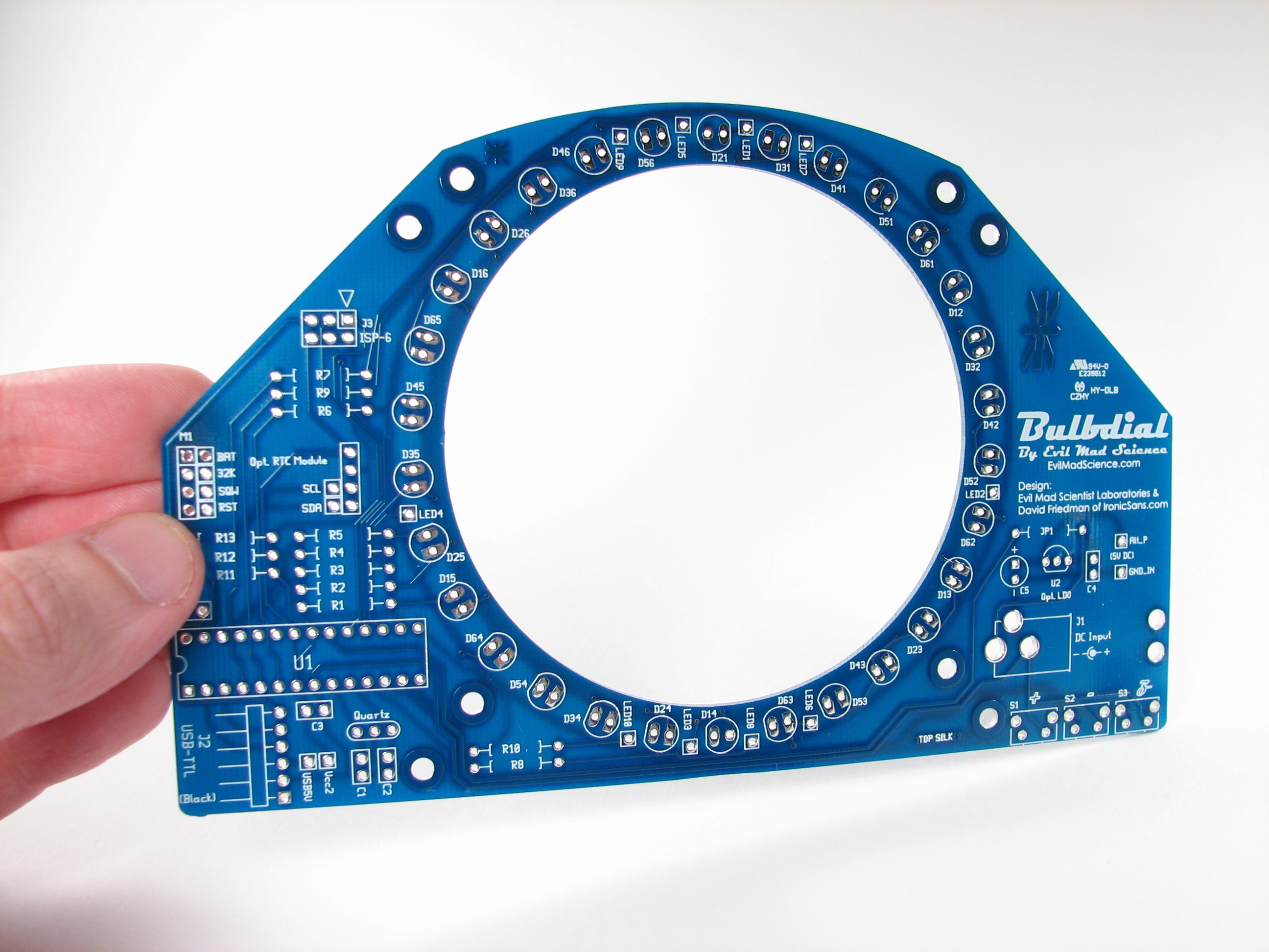
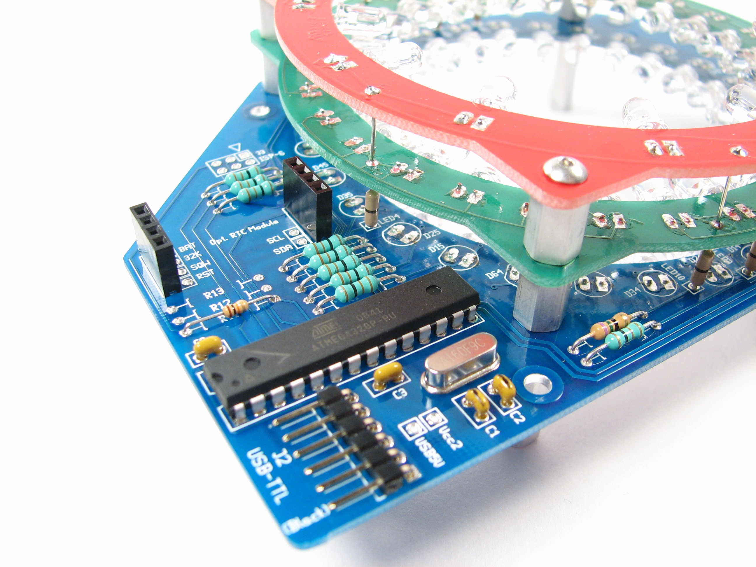
A few big changes. One, we’ve got circuit boards. And wow, have we got circuit boards.
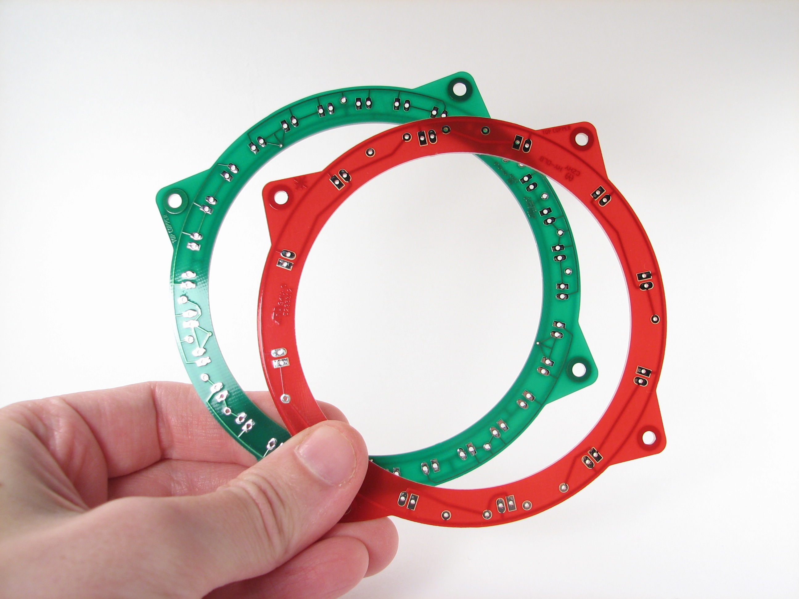
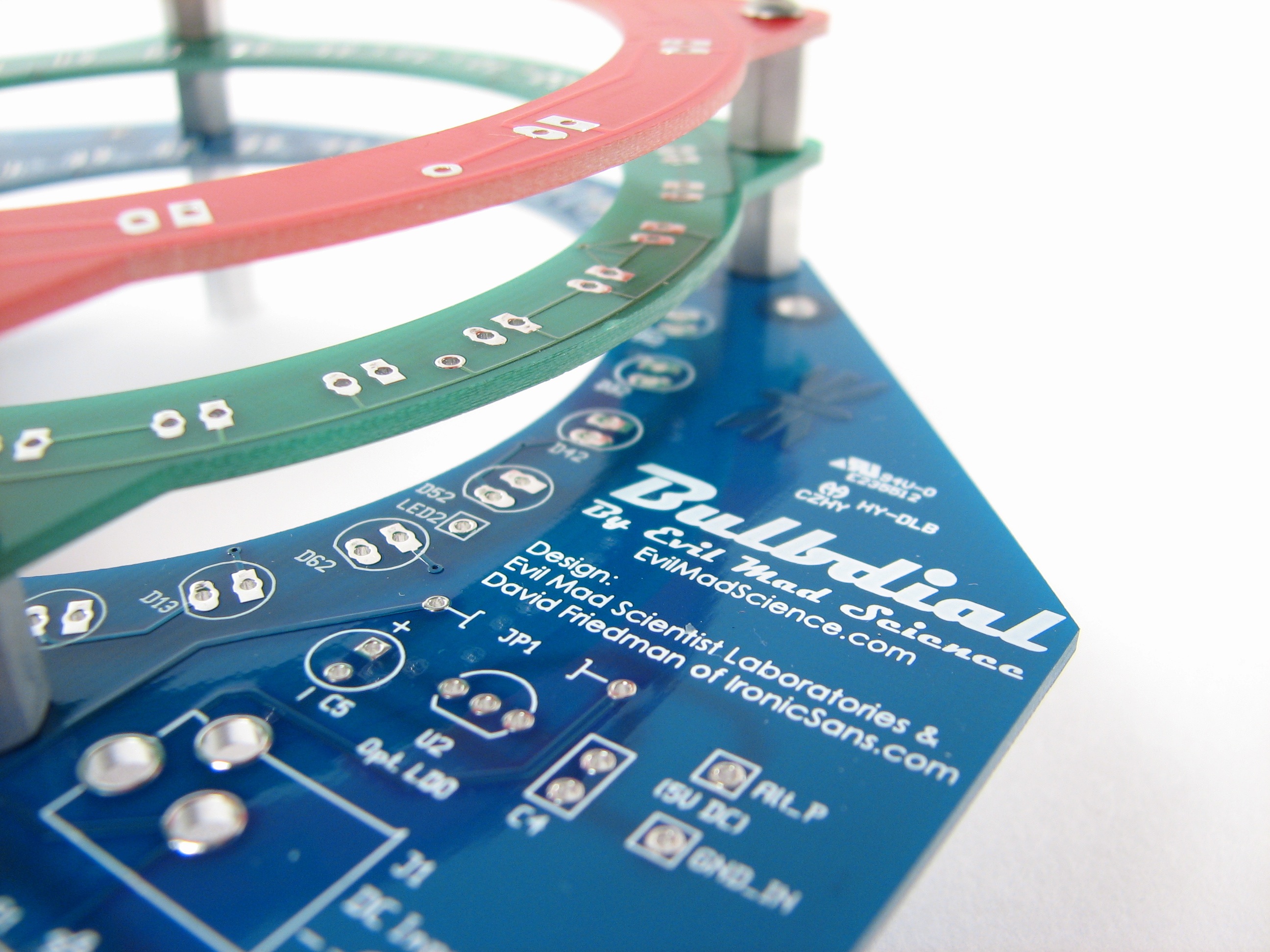
Two, we’ve got a lot more LEDs.
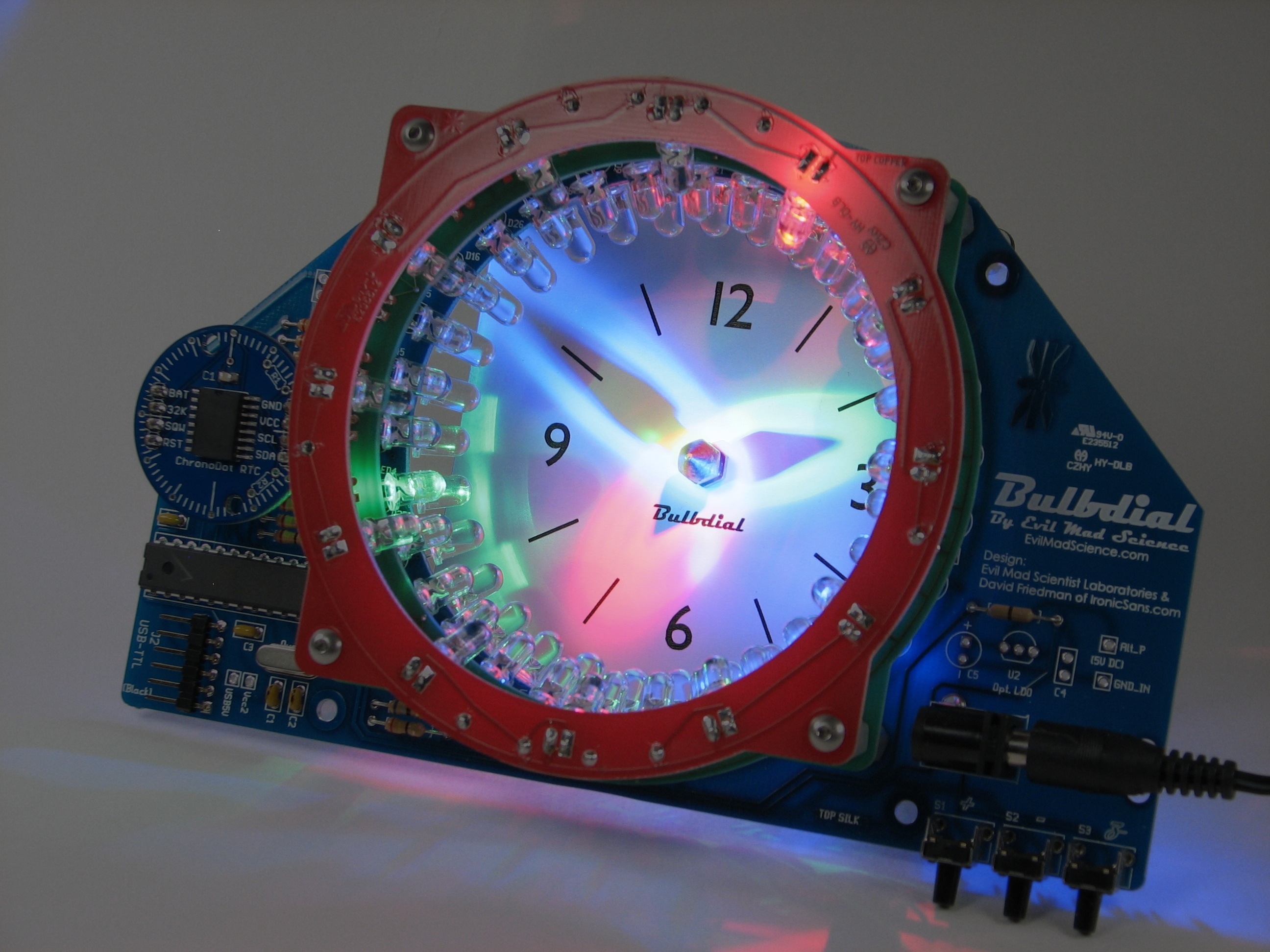
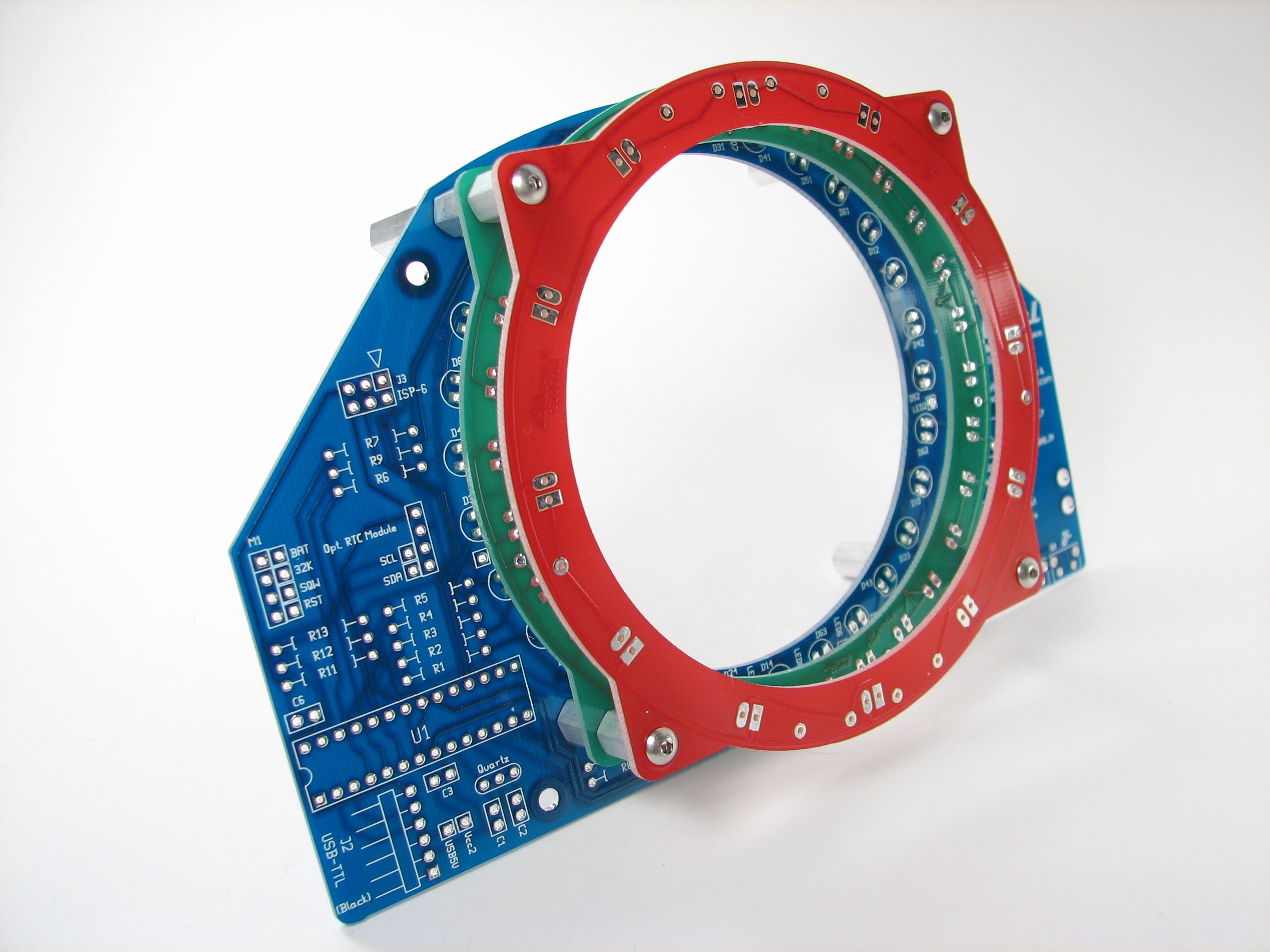
72 LEDs, charlieplexed. This is an efficient arrangement, since only three LEDs (well, maybe five, if fading between two locations) need to be on at a given moment. There are 30 LEDs each on the second and minute rings, and 12 on the hour. The clock changes position every two seconds– fading between positions, so it’s easy to see that the clock moves in real time now. (Embedded video follows; if you can’t see it here, click through to see it at YouTube.)
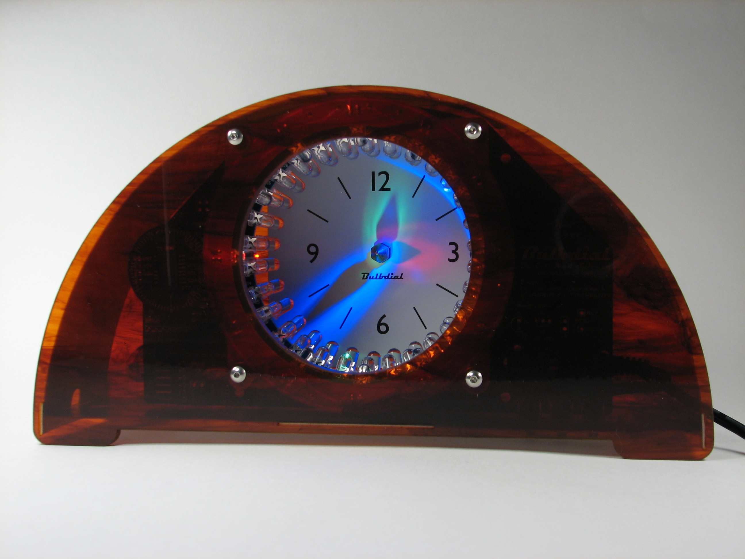
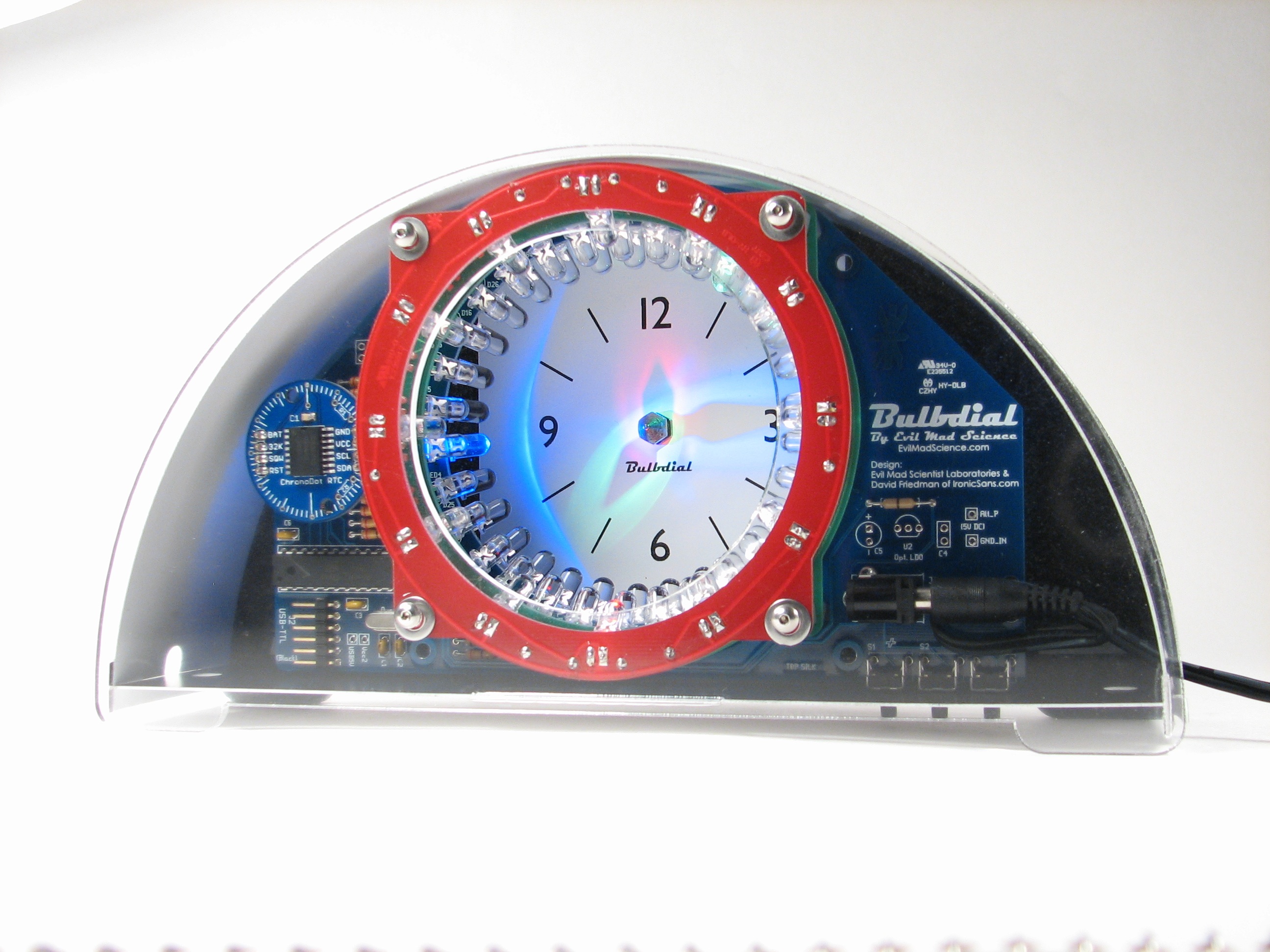
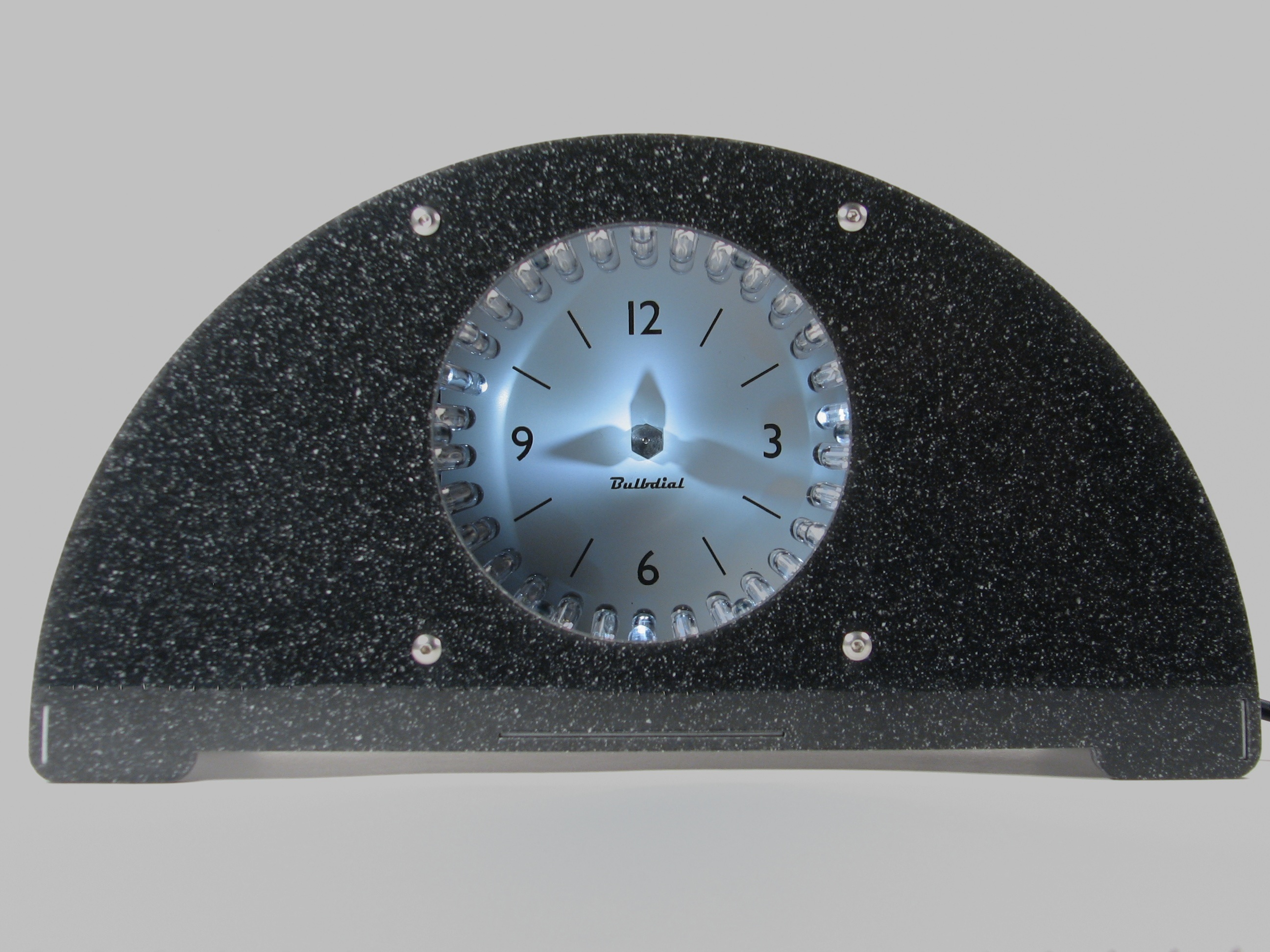
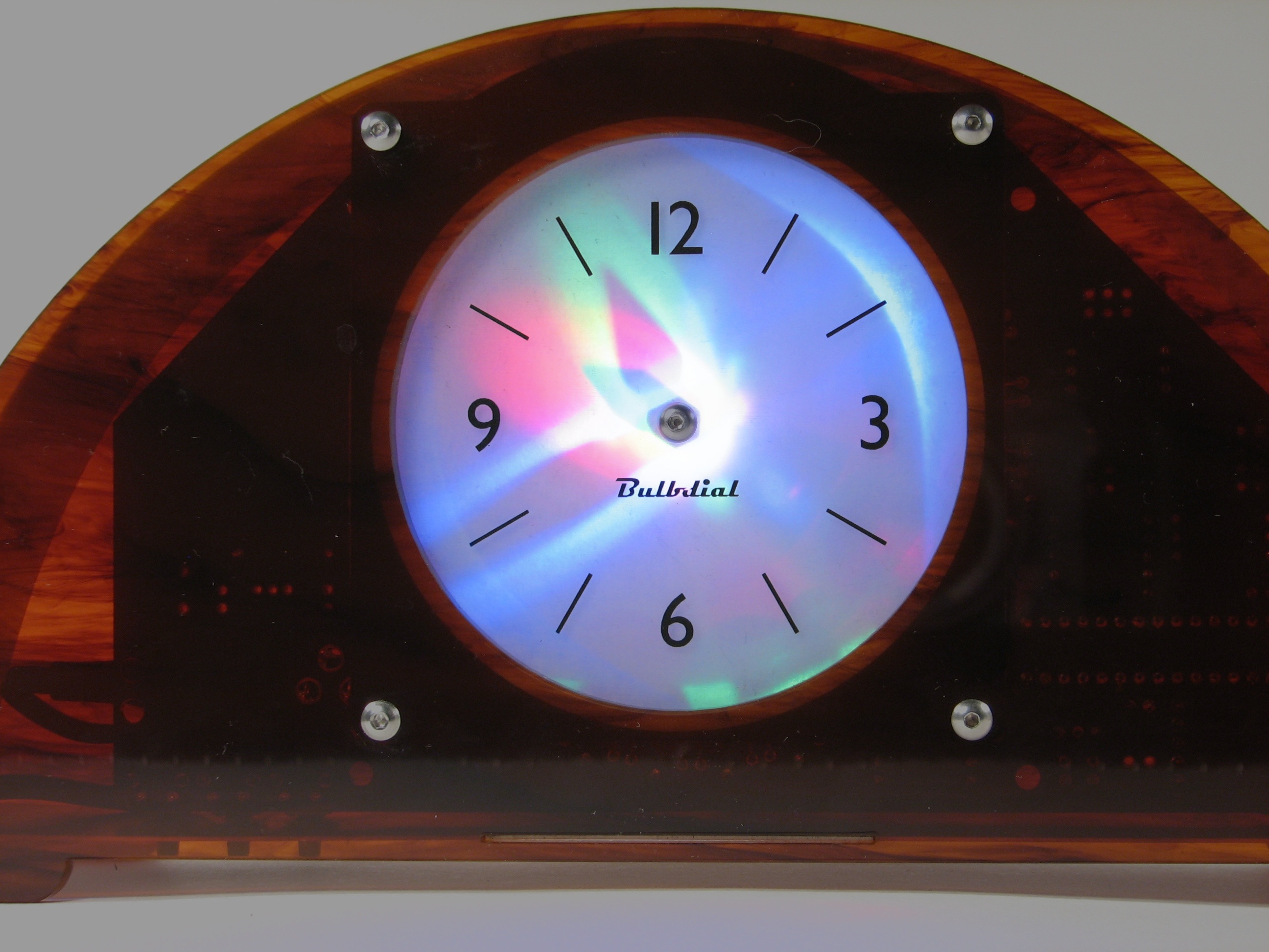
Third, we have a real enclosure.
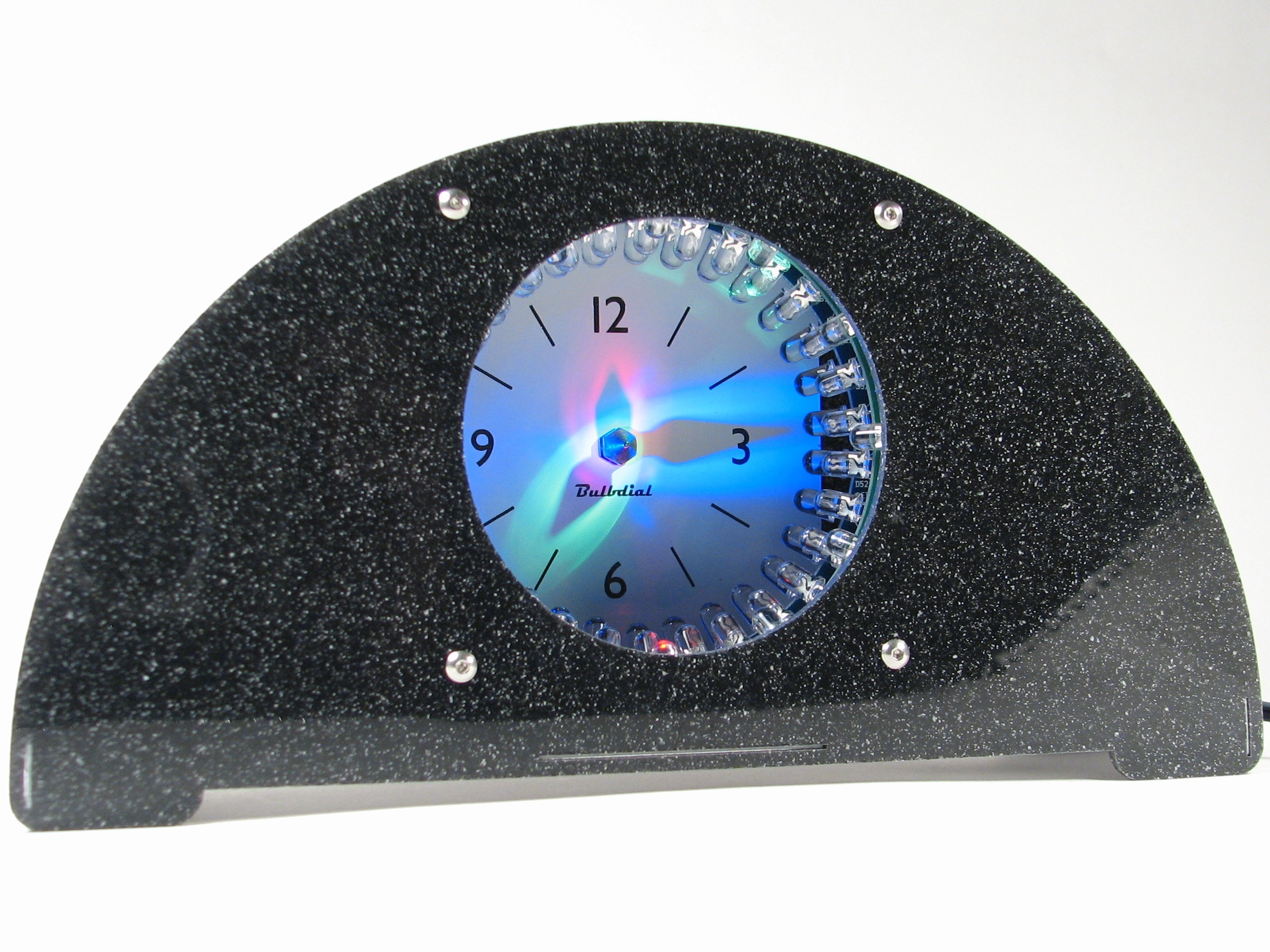
It’s now designed as a mantle or desk clock, with 1/8″ acrylic front and back faces. We found a source of some amazing plastics– iridescent pearl, black-flecked granite, and tortoiseshell, and used those for the faces. We also put together a clear front/black back enclosure, so that you can see our pretty circuit boards.
While the front and back faces are rigid, the top “arch” and bottom pieces are thin, flexible acrylic that bends where we need it to.
Fourth, a plug-in power supply. ‘Nuff said.
Fifth, an option for a real-time clock module with battery backup.
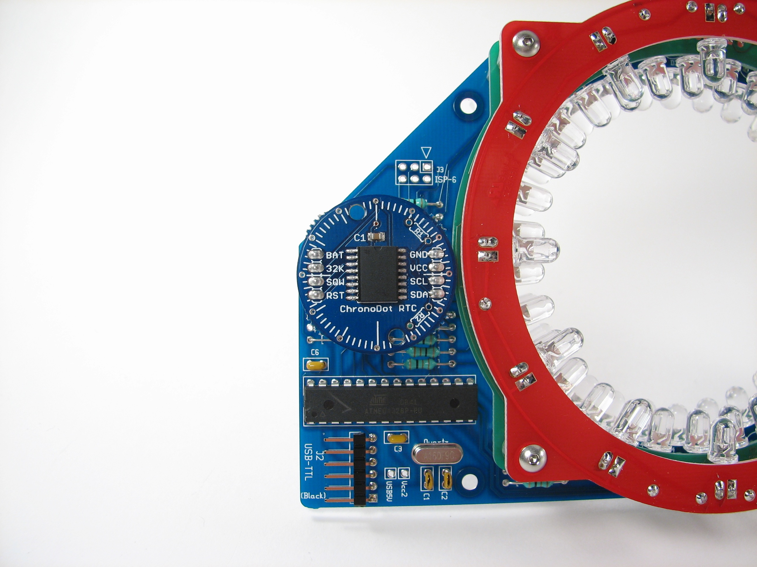
We picked the Chronodot from macetech, which includes a DS3231 chip and a backup battery. The DS3231 is a “high accuracy” clock chip with a built-in temperature-compensated crystal oscillator. Nifty.
Sixth, it’s Arduino compatible, just like Peggy 2 and Meggy Jr RGB. Want to hack it? Piece of cake. Since we’re using the FTDI USB-TTL cable for programming, you can also use that cable to sync the time on the Bulbdial clock, or even to power the Bulbdial via USB.
Seventh, it comes in monochrome. Love it or hate it, it’s there for you to covet or ignore.
Eighth, it’s designed to support a rear-projection mode. We haven’t got this working quite well enough[…] Update: Finally working as of August 2010! (Read about it here.)
Ninth: Pointy gnomon. (Gnomon == the thing in a sundial that casts a shadow.)
And finally, yes, you can get one in time for Christmas.
This is an open source hardware+software project.
Documentation:
Complete bulbdial documentation, including assembly instructions, is now located at the Evil Mad Science Wiki.
Technical Support:
Please direct technical questions and support for existing kits to our Bulbdial Support forum.
Thanks to EMSL for turning my idea into such a great looking reality!
How big is the clock (with the front panel)? 4-5 inches across?
Great job. We’re trying to figure out which color to buy. :-)
With the case, the clock is about 9" wide, 4.5" tall and 2" deep. The clock face is about 3" across.
Looks great! The dark granite in monochrome looks particularly nice.
(Can’t believe how long it took me to realize that "bulbdial" = "bulb" + "dial" – I thought it was some fancy electronics word I didn’t know. ‘Cause, you know, how adjectives end in "al". >.>)
covet covet covet. so very cool.
Video video video. :P
seconded. (although I’ve already ordered mine.)
hear hear. Just a short video showing the "hands" moving would be great.
Patience, good grasshoppers ;)
We’ve got our hands pretty full at the moment– there’s a lot more that we will put up about this project, video included.
—
Windell H. Oskay
drwho(at)evilmadscientist.com
http://www.evilmadscientist.com/
Give me a bunch of $85 EMSL gift certificate, and I’d buy this and only this every single time.
Whoa.
This looks awesome, keep up the good work! :)
Love the retro vibe – even the font reflects it :)
Definitely getting one of these for Christmas (don’t know what color scheme yet.)
I went with the tortoiseshell plastic since it lets you see a hint of what’s inside, without being completely obvious — the completely clear version sort of reminds me of those clear telephones in the 80s. I went with the RGB LEDs so it’s more obvious which is the hours / minutes / seconds.
I think I’ll eventually order a second one, probably in the flecked black plastic with all white LEDs.
I finally went with the tortoiseshell with monochrome LEDs as the best fitting the retro theme. Also, it allows a glimpse at what’s inside without the circuit boards being in your face. My wife’s getting me it for Christmas :)
Awesome stuff! Just ordered one. One question – when you ship it, is the "bulbdial kit" etc. text on the outside box? My wife will probably end up accepting the package and I don’t want her to know what it is :)
Also, did you do this in gschem & pcb as well, and if so are the files going to be available eventually?
>is the “bulbdial kit” etc. text on the outside box?
Here is a sneak peak at the box. This goes in an outer box, that does have our return address on it. Unless your package is going internationally (and has a customs declaration….) there won’t be any outside indication of the contents.
>Also, did you do this in gschem & pcb as well, and if so are the files going to be available eventually?
Yes. :) Open-source hardware FTW.
—
Windell H. Oskay
drwho(at)evilmadscientist.com
http://www.evilmadscientist.com/
Whaa?!, I dunno how I missed that…. :( Thank you for letting us post anonymously, hehe
For me, the clear case with multi-colored LEDs is the only way to go. I mean, there are *multicolored PCBs* to match the different colors of LEDs on that layer. That’s about 20 kinds of cool right there.
*GRIN*
—
Windell H. Oskay
drwho(at)evilmadscientist.com
http://www.evilmadscientist.com/
This is 100 tons of geeky right there, gotta have the clear case to show off just how geeky. That’s what I ordered.
So, is the clock module optional? I.e, if it’s not there, it falls back to counting CPU cycles, and just won’t be very accurate?
If no RTC is detected, the regular clock CPU is indeed used. The chip is running on an external "20 ppm" quartz crystal which is slightly more accurate that the "50 ppm" quartz crystals that we normally use.
A "20 ppm" crystal has accuracy within 20 parts per million when at room temperature, if treated correctly Away from room temperature, this varies *a lot,* but in a normal office, it will do okay.
20 ppm over one day is 20*1e-6*86400 s = 1.7 s. Over one month, that can add up to about a minute or so. So, what you end up with is, really, typical accuracy for any other clock that says "QUARTZ" on it. The Chronodot isn’t much different except that it knows the temperature response of the crystal and tunes the frequency as the temperature varies. Doing this gets the accuracy to about +/- 2 ppm, a factor of 10 or so better. Should lose minutes per year, not minutes per month. Probably more important is that it has a nice battery backup feature. :)
—
Windell H. Oskay
drwho(at)evilmadscientist.com
http://www.evilmadscientist.com/
Ah yes, the battery backup is much more important, so you don’t have to reset it when you move it to a different outlet.
There’s also always the USB-sync option to avoid pressing buttons. :)
—
Windell H. Oskay
drwho(at)evilmadscientist.com
http://www.evilmadscientist.com/
I’m thinking of writing a host program that will use NTP to synchronize the bulbdial clock; that would fix the ‘minutes per day/year’ issue. Of course, if your system time is already synched with NTP, then all the host program would need to do is sync the bulbdial once an hour or so.
I once saw a synchronized manual clock that, when it received a synchronization pulse, would spin the seconds, minutes, and hour hands all the way around the clock (very quickly) to the right position. Thus if the clock needed to gain a second, the second hand would sweep 61 seconds; if the clock needed to lose a second, it would sweep the second hand 59 seconds. That might be an interesting mod for the bulbdial software. Another might be to do something similar with the hour hand — when the clock ticks from 3:59:59 to 4:00:00, quickly spin the minute hand around 61 minutes instead of 1 minute, before spinning the hour from 3 to 4.
>I’m thinking of writing a host program that will use NTP to synchronize the bulbdial clock;
You certainly can, but I’m not sure that there’s a pressing need to do so. If you want to hook the computer to a network, you’re going to need a physical connection to the computer like the USB-TTL cable that we normally use. So long as you have that, you can use the existing time-sync program to sync the Bulbdial clock to your PC’s time, and most PCs already support automatic NTP sync. So… we already do this, in effect.
—
Windell H. Oskay
drwho(at)evilmadscientist.com
http://www.evilmadscientist.com/
it would be cool if you could add a module that could recover the atomic time from the WWV shortwave broadcasts. that would go along with the retro look, but i suppose wifi + an ntp client would be a more modern equivalent.
I’ve gotten, and built my bulbdial… I love it, it’s wonderful… however, in one way, I just have to wonder, why is it that more people, when building clocks, don’t take advantage of a very reliable time source… the 60 hz that’s available from all the outlets in north america, or 50hz around most of the rest of the world, while it may drift back an forth a little, in the long term, it’s very stable. way back when, I built an alarm clock and that was usually within a second or so of being correct. just a thought, use a ac adapter, use the 60hz for the time base, and only use a crystal for when you’re on battery.
That’s actually not very difficult to do, but it is definitely not *safe* for end-users (many of whom are young and/or fairly new to soldering). By contrast a short-circuit protected 5 V supply is quite tame. Simple mains-connected supplies are not efficient, and they need to be differently configured for operation in different countries, because of the voltage differences. The 5 V supply also works worldwide without modifications, and at a higher efficiency everywhere. So… it’s a nice idea, but it’s actually suboptimal for a clock kit.
—
Windell H. Oskay
drwho(at)evilmadscientist.com
http://www.evilmadscientist.com/
WANT!!!
This hits a wonderful "sweet spot" of Artsy, Techy, and Affordability… Very nice!
Would you consider posting technical/tutorial info on how you managed to get the "complex" shaped PCBs manufactured?
I hope you figured out something interesting to do on the circular "cutout" pieces.
How about a youtube video so we can see it in action.
How is it in high ambient light conditions?
Obviously the LEDs are bright, but can be overwhelmed in a sufficiently environment. Should be good in most office environments, but not in direct sunlight. (Consider a sundial!)
That’s one of the reason that we have dark cases available, where the visible clock face is recessed– the dark cases provide pretty good shade, actually.
—
Windell H. Oskay
drwho(at)evilmadscientist.com
http://www.evilmadscientist.com/
As far as diffusion for the rear project mode. have you tried using diffusing layers from an lcd? i used to use them to create soft lights. also might try adding a fresnel before the diffusion layer.
Nope, haven’t tried this. Is it available commercially in moderate quantity? Any idea where I could get some to sample?
—
Windell H. Oskay
drwho(at)evilmadscientist.com
http://www.evilmadscientist.com/
This is so cool I just had to buy a kit with all the extras. Great price for such a neat device. Are there any components that are finnicky or easy to fry when soldering? I’m alright with a soldering iron although I have a feeling after soldering 72 LEDs I’m going to be a pro.
>Are there any components that are finnicky or easy to fry when soldering?
Nothing unusual– just LEDs and one integrated circuit. It’s easy to *not* damage them if you make sure that the tip of your soldering iron is tinned well and you limit soldering time to reasonable amounts. Our instructions do provide suggestions which genuinely seem to help folks avoid trouble with soldering. :)
—
Windell H. Oskay
drwho(at)evilmadscientist.com
http://www.evilmadscientist.com/
Wow, that’s beautiful! For the case, what about a translucent/frosted gray option?
We have some smoke-gray plastic, but I don’t think that’s what you mean– can you please clarify?
—
Windell H. Oskay
drwho(at)evilmadscientist.com
http://www.evilmadscientist.com/
Just finished mine last night and I have to say, awesome kit! Straightforward, clear instructions and high-quality materials, not to mention it looks friggin’ Nice!
I am curious as to when the source code will be posted (or, if it has been posted, where I could find it)? Thanks!
Sweet– thanks!
The source code is actually posted at the end of the article that these very comments are attached to; here is a direct link to the end of the article.
—
Windell H. Oskay
drwho(at)evilmadscientist.com
http://www.evilmadscientist.com/
I took about 6-hours to build mine, because I am a perfectionist. I wanted to get all of the flux off of the circuit boards, and spent a lot of time getting the LED’s perfectly aimed etc. I am very impressed with the quality of the kit and the documentation. The finished clock looks and works flawlessly, and is very
pleasing to look at. One would never guess it is made from a kit or that it did not come from a classy interior decor store.
I did have one question, however. I have programmed a lot of Atmel parts with the ISP connector, and AVR-Studio, but have never used the Arduino programs. Can the program be copied to a HEX file with the ISP connector before playing with the Arduino programs so that I can restore everything if I get into trouble with the Arduino sketch loader and source code manipulation? (Are any of the program lock bits activated to prevent this?) Thanks
Great– we’re always happy to hear reports of smooth sailing. :)
The kit can be programmed through a regular ISP programmer or through the USB-TTL cable. Programming through the bootloader (via USB-TTL) cable is "safe" — it cannot overwrite the fuses or bootloader, as the lock bits are set to standard "Arduino" values.
Programming with the ISP programmer is not as safe– as you probably know, there are potential ways to set the fuses that are not recoverable by in-system programming. That said, you certainly can use the ISP to read out the full flash and back it up and/or rewrite it. You can also reprogram the default software using the ISP programmer directly within the Arduino environment, or use the Arduino stand-alone makefile to program the kit with the ISP programmer from the command line (using win-avr or the like).
—
Windell H. Oskay
drwho(at)evilmadscientist.com
http://www.evilmadscientist.com/
Since I put a 28-pin socket in the microprocessor spot, I was able to try out this ISP backup technique, and programmed a spare AtMega168 with all of the same software. Now I can tinker with the Arduino programming gadgets, and source code experiments, with total confidence that I will never lose the ability to restore the system to its "Factory" configuration. This is the coolest kit you guys have ever made! Thanks
When you said:
You can also reprogram the default software using the ISP programmer directly within the Arduino environment, or use the Arduino stand-alone makefile to program the kit with the ISP programmer from the command line (using win-avr or the like).
What kind of programming connection is required to use the ISP connector within the Arduino environment. I have a JTAG-ICE-Mark-II development kit with will program ALL 8-bit and ARM type Atmel devices. Will the Arduino development kit work properly with that device, or do I need to get one of those little USB-IDE kits?
Also I wanted to ask another question. Is the makefile that you referred to as the "Arduino standalone makefile" a standard makefile available somewhere on the Arduino web site, or is this a custom designed makefile that you created to compile your Application along with the bootloader. If custom will you post it? Also when you are running the Arduino IDE and click on the "Program Boot Loader" button, do you have to do that programming with the ISP connector? I would think so, since the serial port programming features require that the boot loader be running, in order to function. Does that IDE "Program Boot Loader" operation also set the appropriate fuse bits to properly enable, and protect the boot section of memory?
I answered my own question. The Arduino.exe program will not use the JTAG-ICE MKII programmer, and doesn’t event seem to work properly with the AVR-ISP MKII, which IS listed on it’s menu. But I was able to get the bootloader properly installed into my COPY AtMega168 by using AVR-Studio. I completely erased the part, and reset all of the fuses back to the default values before programming the hex file which contained both the application and bootloader. Then I carefully set ALL of the fuses to match the original AtMega168, and now everything works including the boot loader. Whew! Now I can begin to experiment with fun modifications to the application using the Arduino source pde file and the Arduino IDE. Yea!
You do seem to be doing pretty well on your own. :)
One of the things that I like about the Arduino environment is the large amount of information out there about it. There *are* ways to do the full programming through the ISP connector without the bootloader, using the standalone makefile (found at hardware/cores/arduino/Makefile within the Arduino folder). A potential advantage to this is that your clock will no longer have the two-second bootloader delay at turn-on.
Also: Please direct future technical and support questions to our support forum, which is located here. The forums have a much better structure for answering questions within threads.
—
Windell H. Oskay
drwho(at)evilmadscientist.com
http://www.evilmadscientist.com/
I just wanted to post a quick review of the kit. I put mine together last night.
I’m a total noob at soldering. I have done a few very simple projects here and there, but nothing of this scope. I purchased some perf board, and practiced with the soldering iron and hook up wire until I was comfortable with it and getting good, consistent results.
Time to put it together: right around 4 hours.
Most difficult part: Aligning the green LEDs. My fingers just couldn’t get in the space to move them, and they were all off center.
Favorite part: Powering it up the first time, and nothing caught fire, sparked, or smoked. Just some blue LEDs lit up as expected.
Biggest ooops: The headers for the chronodot are way crooked despite my best efforts.
It is significantly brighter than the photos make it out to be. Even in it’s dimmest mode, it’s easy to see.
Instructions were very clear. Only exception to that was concerning the resistor in R10 (page 8 and 9 of the instructions). It’s a different resistor between the RGB and monochrome kits, and the instructions got a little confusing between the two. I would suggest maybe changing the order in the instructions to say "install resistors in R1-R9 first, then in R10, install resistor A for the RGB or resistor B for the monochrome kit."
Overall, this is one freaking sweet clock. This one is a Christmas present for a friend, but I’ll be getting a second one for myself in a few weeks. I did find it a little unnerving that I didn’t hear the normal clock tick. For some reason, that just caught me off guard.
Thanks for making such a killer kit. Definitely well worth the money.
Before I say anything else, I just want to thank you for providing excellent technical documentation, and open source files for this kit. (Software, Schematics, Instructions, etc.) After reading the schematic, I did notice a small typo on the third page. The name in the Title Box says "Bulbdial Clock: Minute PCB" and the schematic file name in the file box, says "bdminute.sch" These should read "Bulbdial Clock: Hour PCB" and "bdhour.sch" to accurately represent their actual design function. I know that you probably copied some things from the Minute
page, and just forgot to update the third page to reflect the name difference for the Hours page.
Thanks– and good catch!
(We’re also updating the instructions now with a bunch of first-round feedback, typo correction, and so forth.)
—
Windell H. Oskay
drwho(at)evilmadscientist.com
http://www.evilmadscientist.com/
If you make a new batch of circuit boards, there were some small inconsistencies in the solder mask for some of the pads around the "Green Ring". It doesn’t cause any problem, with soldering, but the "Unmasked Area" of some of the pads around the Green ring are not the same as the rest. If you are curious.
I’ve just looked at one of the boards, and I’m not sure what you’re referring to– can you please clarify?
—
Windell H. Oskay
drwho(at)evilmadscientist.com
http://www.evilmadscientist.com/
I remember that when I soldered the LED’s there were two pads that had a circular hole in the solder mask, instead of the typical Oval or Rectangular holes. The pads underneath the solder mask were consistently Oval or Rectangular, but the solder would not flow to the full Oval or Rectangular pad shape on these two pads. I believe these pads were on the "Green Ring" if I remember correctly. On these two pads the circular hole in the solder mask was large enough to make a good solder joint, so there is no problem with the layout, but there was a small inconsistency that I thought you might want to be aware of if you ever get around to ordering more boards.
Ah– yes, a couple of the pads that should be square are small circles instead, on a couple of the boards. (A very minor design goof.)
—
Windell H. Oskay
drwho(at)evilmadscientist.com
http://www.evilmadscientist.com/
Hi, I just got one as a christmas present! However, I was wondering if you’ll be posting the drawings for the case? I have access to a laser cutter and would like to make my own.
Keep up the great work!
I have used AVR Studio, and designed lots of gadgets with Atmel processors, but have never used any of the arduino tools. I got the arduino IDE installed and included the DateTime libraries. When I compile the Beady1.pde sketch it compiles just fine, and When I say upload it seems to do something, but after the upload completes, the following message appears in the error window at the bottom of the IDE:
avrdude: stk500_getsync(): not in sync: resp=0x00
avrdude: stk500_disable(): protocol error, expect=0x14, resp=0x51
Are these messages normal?
I couldn’t get the processing sketches to run? I have been banging my head against this problem for several hours. In linux I found a separate app for processing, but didn’t find one in windows. My debian sarge linux distro is too old to accomodate the latest JRE and other tools, so I will have to try a newer linux to
get that stuff working, but I thought I might get it to work in windows. When I
googled for "Processing for Windows" the download did not include any runnable
IDE applications to handle processing only a few java library jar files that were to be inserted into the Sketchbook/librarys directory. Do you run processing sketches with the arduino IDE in the windows environment, or is there some other IDE that I haven’t been able to find yet?
> the following message appears in the error window at the bottom of the IDE:
> avrdude: stk500_getsync(): not in sync: resp=0x00
This is a “blanket” error that covers almost any kind of bad connection.
Check that the USB-TTL cable is plugged in the right way. Also make sure that the clock is powered and running when you start. Also make sure that the correct serial port and board type are selected in the Arduino tools menu. It is also possible in some circumstances that you need to install a driver (the FTDI VCP –“Virtual COM port” driver), if you can’t get it to show up in your menu. Also (on windows machines) you sometimes need to adjusting your port settings: Device Manager – Comm Ports – USB Serial Port – Port Settings – Advanced button – Set RTS On Close.
The Processing application is available for download here. It’s a *regular application*– you shouldn’t need to mess with it –and there are versions for Mac, Windows, and Linux. When you run it, it looks just like the Arduino IDE (or rather, the other way around– the Arduino app is based on the Processing app.) Use that IDE to open up the sync program and run it.
—
Windell H. Oskay
drwho(at)evilmadscientist.com
http://www.evilmadscientist.com/
I figured out why the upload wasn’t working. I had made what I thought was a perfect copy of the firmware in the AtMega168 and was using the processor with the copy. Apparently my copy of the firmware didn’t include the bootloader, or somehow I didn’t get all of the fuses set the same to properly activate the bootloader or something like that. Anyway, when I put the original AtMega168 processor back into the socket, then the upload worked as expected.
Now I just have to figure out why my copy copied bootloader isn’t working right.
I got it working now. On my computer with a newer linux distro I got it all to work
just fine. I still don’t know how to make it work in Windoze though.
This is truly a gorgeous kit. Everything is done so professionally, and is so well thought out. It was easy and fun to build, and everyone I showed it to said "I Want One Too". Thanks
Ordered one of these and I’m having a great time helping my 12 year old son learn to solder and build the kit. Great design and good instructions for assembly. Thanks EMSL!
It’s a great kit with Heathkit spirit inside.
Season’s grettings to all
Kuroneko
Kit went together great, assembled one monochome kit and a color kit. The second kit I built, I recorded a time elapsed photo set that I posted on youtube: [link:]http://www.youtube.com/watch?v=hJjVM5fW830
Just finished building mine. I must say that the photos and video don’t do it justice… it looks awesome. Very easy build.
I built mine last week and am very impressed with the kit and finished product. The instructions were fantastic and it was the most fun I’ve had building an electronics kit. Thanks!
Mine arrived on the 23rd. I was thinking about putting it together and giving it to my Dad for xmas, but didn’t really have time. I had time over the weekend, and it took me about 3 hours. I didn’t time it, but I listened to all of the "Science Friday" podcast (about 2 hours) and "Wait Wait Don’t Tell Me" (about an hour). It’s mine now, I gave something else to Dad.
I like how you didn’t kill any trees for the instructions. I just brought my laptop down to the shop, and displayed the instructions on that. Thanks for formatting it "landscape", it worked better that way.
No problems at all. I had a little problem with my first Larson Scanner kit and that helped brush the rust off my soldering skillz.
On the hour ring, more LEDs.
Because there are only the 12 LEDs, the hour does not shift until the next hour. 2:55 and the hour hand is solidly on the 2. Even double the LEDs so that at 1/2 past the hour shadow is midway between the hours.
The other is to bring the TTL and power connectors out the back or side so to swap cables I don’t have to unscrew the case.
You need to keep in mind that this a digital clock with hands. You read hour, then minute, then second. At 2:55, the time displayed is 2:55– the hour hand doesn’t advance until the hour advances. It’s not an analog clock, and yes, it will get confusing if you pretend that it is.
If we changed the design so that it could display a time of (for example) 2.5:55, it simply doesn’t make sense, because the hour hand shouldn’t be halfway between numbers if it’s almost on the hour. It would just appear to be a broken clock. You would need much higher resolution– maybe 60 LEDs –to communicate the time in a somewhat "analog" fashion. That might be feasible on a considerably larger clock.
One thing that you might consider instead is reprogramming it to fade between hour locations over the course of a full hour.
>The other is to bring the TTL and power connectors out the back or side so to swap cables
>I don’t have to unscrew the case.
Our plan is ultimately to finish up the "rear projection" option– which means that the back side of one might be the front side of another– so we’re definitely not going to do it that way.
If you’re swapping cables on a regular basis (and I’m *really* not sure why you would want to do that), try leaving off either the arch cover or the base cover, according to your taste. Our original plan was to route the wires down through the base cover; you can cut larger openings for them there, and there are extra holes on the main PCB that you can use to constrain the cable with a cable tie.
—
Windell H. Oskay
drwho(at)evilmadscientist.com
http://www.evilmadscientist.com/
> If we changed the design so that it could display a time of (for example) 2.5:55,
> it simply doesn’t make sense, because the hour hand shouldn’t be halfway
> between numbers if it’s almost on the hour. It would just appear to be a broken
> clock. You would need much higher resolution– maybe 60 LEDs –to
> communicate the time in a somewhat "analog" fashion. That might be feasible
> on a considerably larger clock.
I think it might look right if you displayed "2" from 1:45 to 2:15, and then "2.5" from 2:15 to 2:45.
> One thing that you might consider instead is reprogramming it to fade
> between hour locations over the course of a full hour.
That’s the other thing I thought of. If anybody does this please post the code, I’d like to see what it looks like!
>I think it might look right if you displayed "2" from 1:45 to 2:15, and then "2.5" from 2:15 to 2:45.
I do see what you are saying now. For better or worse, the electronics are somewhat at their limit without adding additional driver chips… adding another dozen LEDs would probably end up making the kit disproportionately more complex and expensive.
> That’s the other thing I thought of. If anybody does this please post the code, I’d like to see what it looks like!
Shouldn’t be too hard to write example code for that– but it would be better to move this discussion to the forum. :)
—
Windell H. Oskay
drwho(at)evilmadscientist.com
http://www.evilmadscientist.com/
I have found that the arch cover can be removed and reinstalled in a matter of seconds, by simply flexing the front and back covers just a little. That way you don’t have to take out the screws at all! Makes attaching and removing cables a snap.
I made my clock today. I love it! Here are my photos:
http://www.flickr.com/photos/23731721@N04/sets/72157623060743479/
Thank you for making such a great kit! Easy to put together, not too time consuming, but a feeling of accomplishment once finished.
In the end of article was sentense "Additional design files (including PCB files) will be posted here over the next couple of weeks." Where i can get (download) it? Or maybe it will be posted soon?
What is the "Hello Bulbdial" code?
It’s a simple demo program, which is there to serve as a starting point if you want to write your own Bulbdial Clock code from scratch. We put it together by request, since some folks found the full clock code a bit complex for a starting point.
Windell H. Oskay
drwho(at)evilmadscientist.com
http://www.evilmadscientist.com/
I have built many electronic clock kits and I have a background in circuit testing and assembly. The Bulbdial clock is not only one of the most well-designed kits I’ve assembled, but the assembly instructions and packaging make it difficult to make a serious mistake. They even included a lead bending jig for the LED’s. It is one of those clocks that you find yourself staring at, and it looks even cooler now that I have the rear projection screen attached. And no, they did not pay me to write this!
Is there a way to attach a light dependent resistor, for low light dimming?
Or just change the program for a dim every 18 hrs?
>Is there a way to attach a light dependent resistor, for low light dimming?
There are multiple levels of brightness available for different light conditions, including display-off. If you’re just going to use it at night, you can leave it set to the lowest level, or you can press the button to switch it.
But to answer your question, yes. There are three communication interfaces provided (serial, ISP, I2C). If you don’t need one or more of these interfaces, you can repurpose the relevant pins to accept input from any number of sources. If you aren’t using the chronodot (or another I2C based RTC), I’d suggest using pins 27 and/or 28 as analog inputs for your LDR-derived signal. You’ll still need to alter the program to read that input and respond to it.
>Or just change the program for a dim every 18 hrs?
Yes, that’s easy enough to do as well.
Windell H. Oskay
drwho(at)evilmadscientist.com
http://www.evilmadscientist.com/
Can you make the bulbdial an alarm clock? As an added feature you should add an alarm buzzer with time setting switch and change the software to play a wake-up buzzer type song. Also a volume potentiometer would be helpful .
It’s an open-source project. If you want alarm functionality and a buzzer, then have at it! :)