


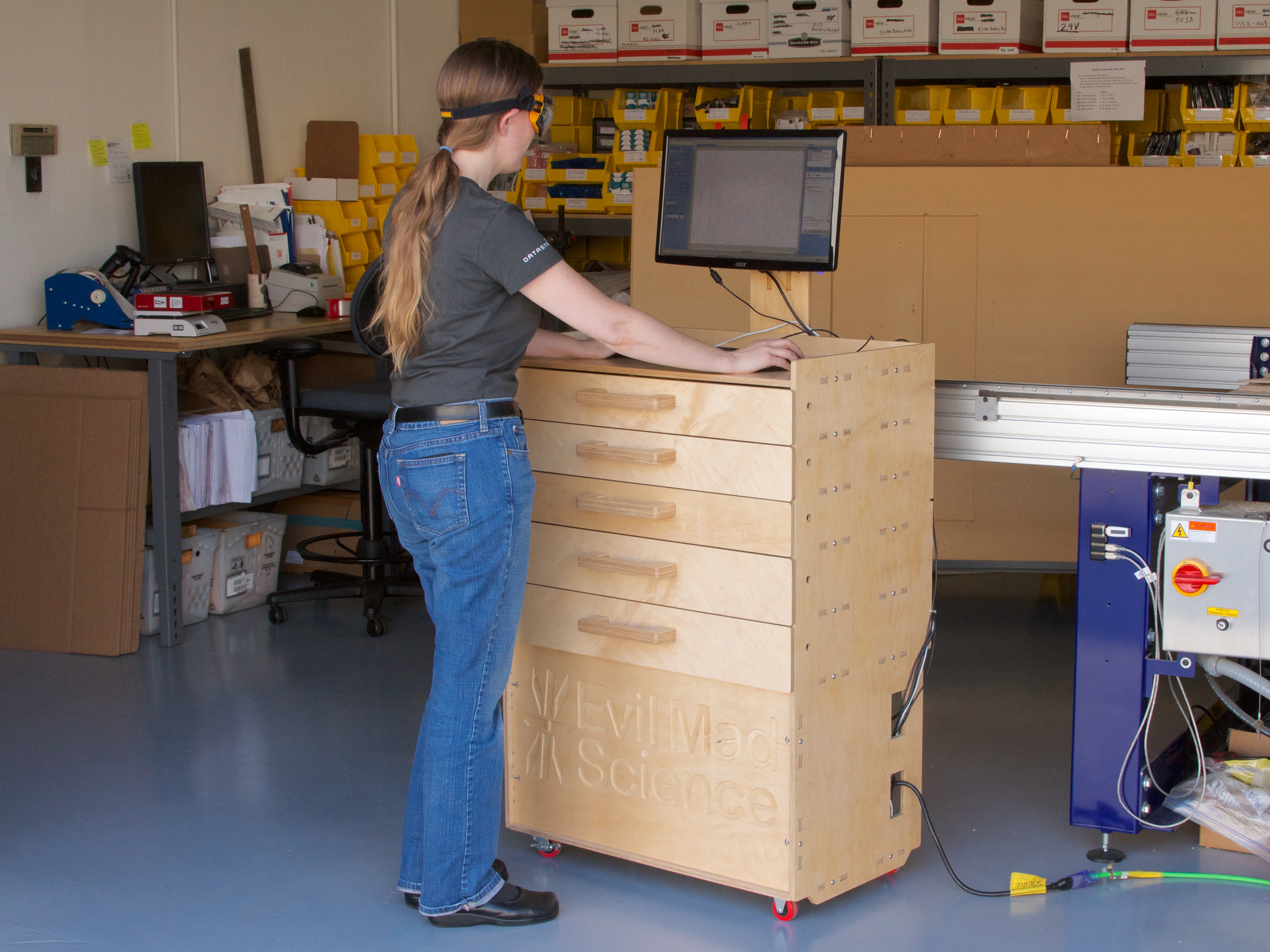
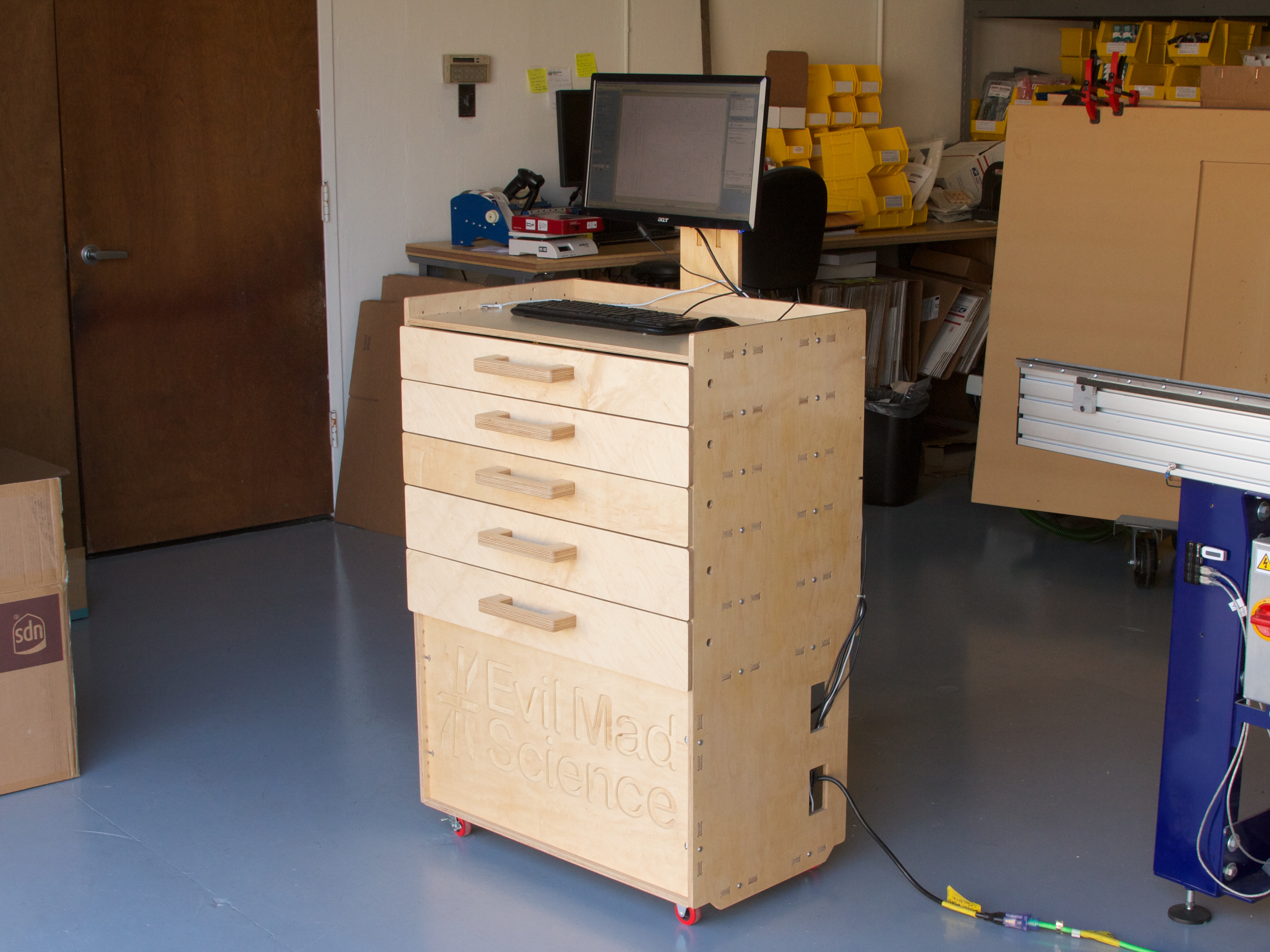
Recently we needed a sturdy, standing-height computer workstation for our workshop. So, we designed and built one. It has turned out to be one of the most useful things that we’ve ever made. And now, we’re releasing our design, so you can build one too!
A little background: This computer station is the one that we use to operate our CNC router. Previously, we had been operating that machine from a laptop on a rolling tool chest. While having a tool chest handy was great, the laptop wasn’t, and the height was backache-inducingly awkward. Once we swapped the laptop out for a desktop computer that didn’t fit on the tool chest, we needed a new solution. We needed a new computer workstation that would actually fit the computer, be comfortable for working at standing height, be sturdy enough for use in the workshop, roll where we needed it to, and offer a decent amount of storage space for tooling and supplies.
Our workstation is CNC-cut from half-inch plywood. It is rock-solid sturdy, yet comes apart easily for transport or modifications. It features a main computer bay with an optional door, five spacious drawers that can’t fall out, enough room on top to comfortably fit a laptop (in addition to the main computer), stainless hardware, polyurethane casters, and a stiff vertical “neck” that supports a swing-arm VESA monitor mount for the main computer.
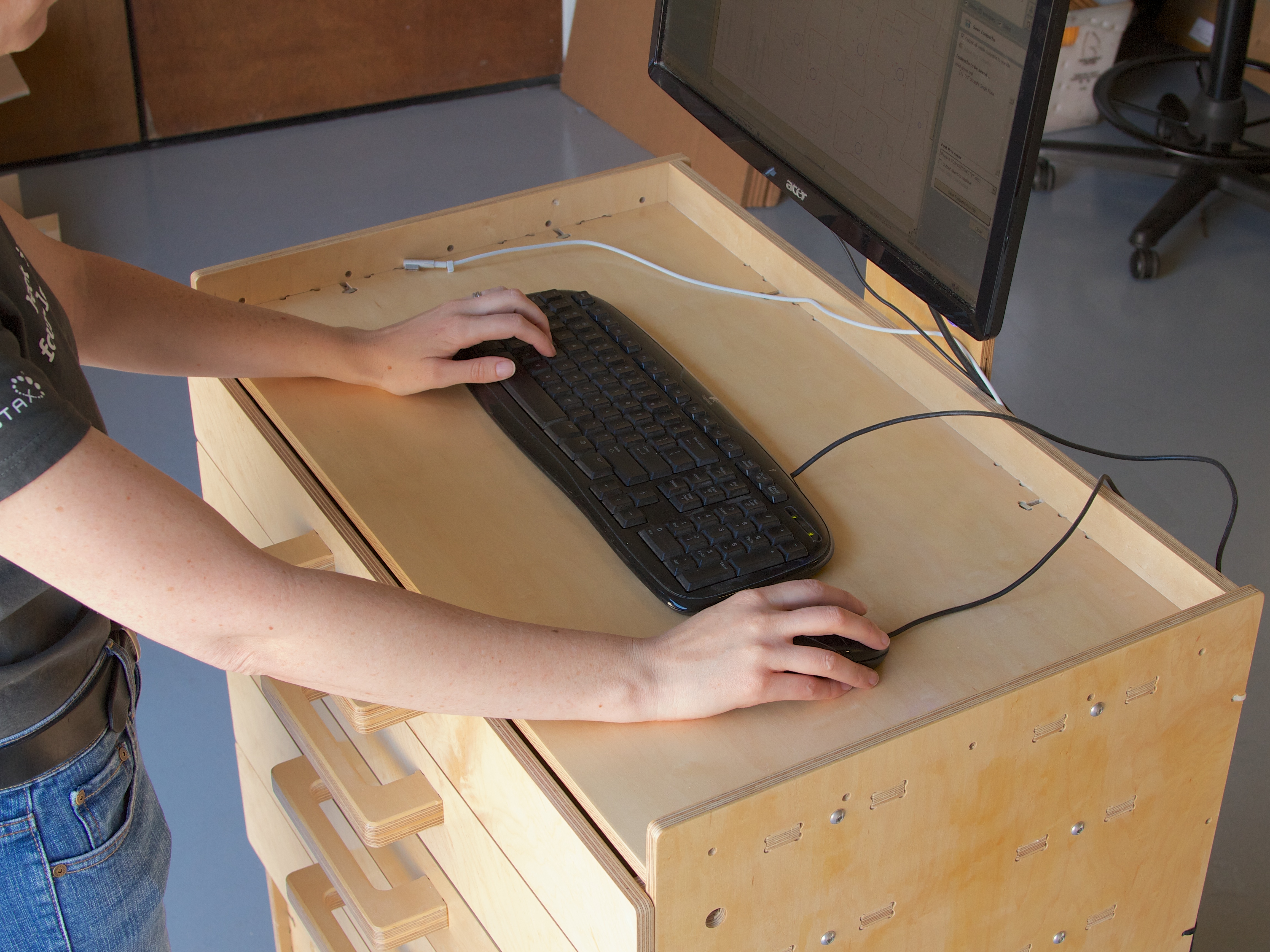
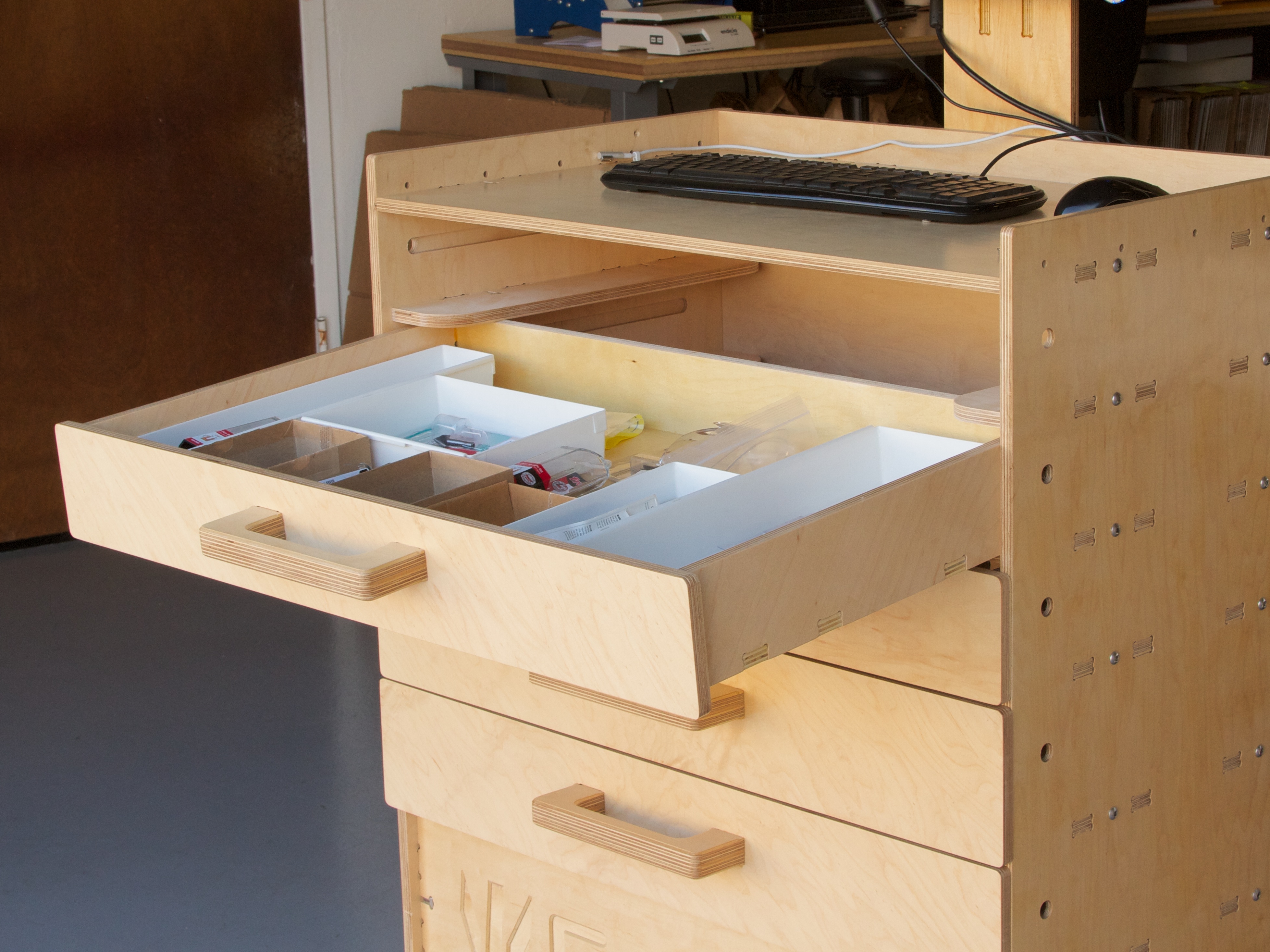
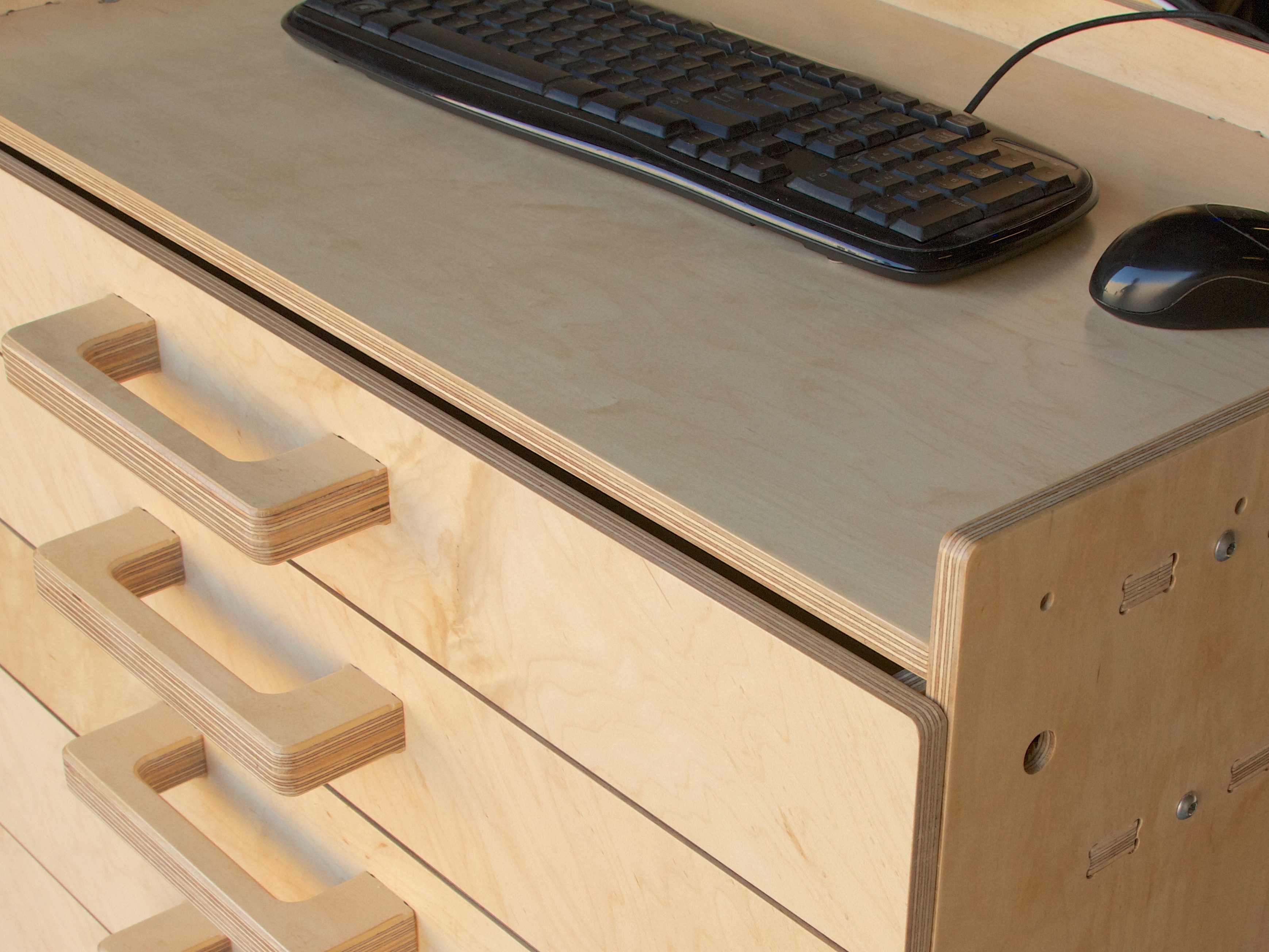
The top deck of the workstation is a flat surface 29 inches wide and 18 inches deep, situated 42 inches above the ground. There’s ample room for a keyboard and mouse, as well as the occasional tool or notebook, and a little wall around the sides to keep everything in place.
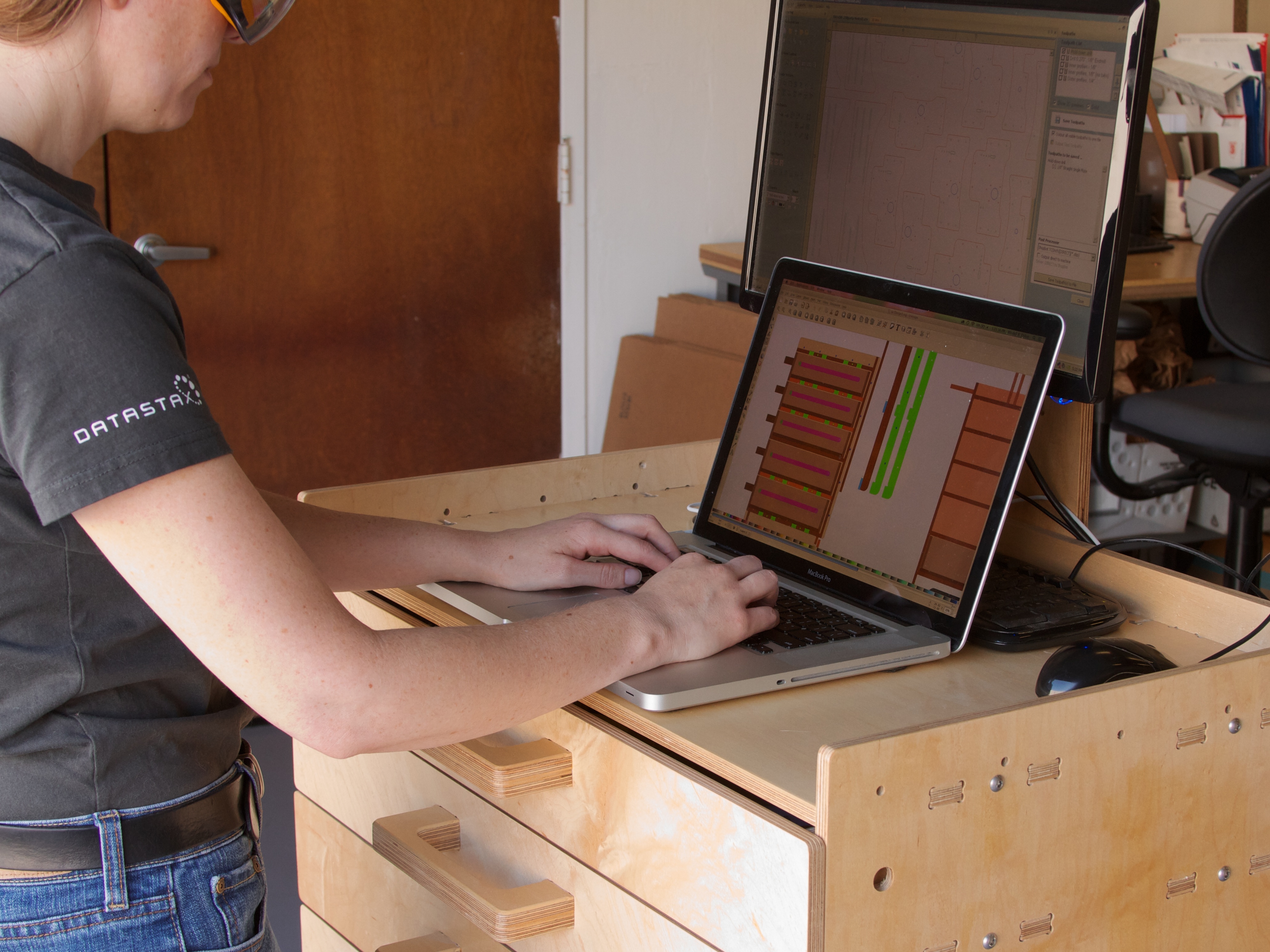
Perhaps most importantly (and as we mentioned), there’s room to fit a second laptop up on top.
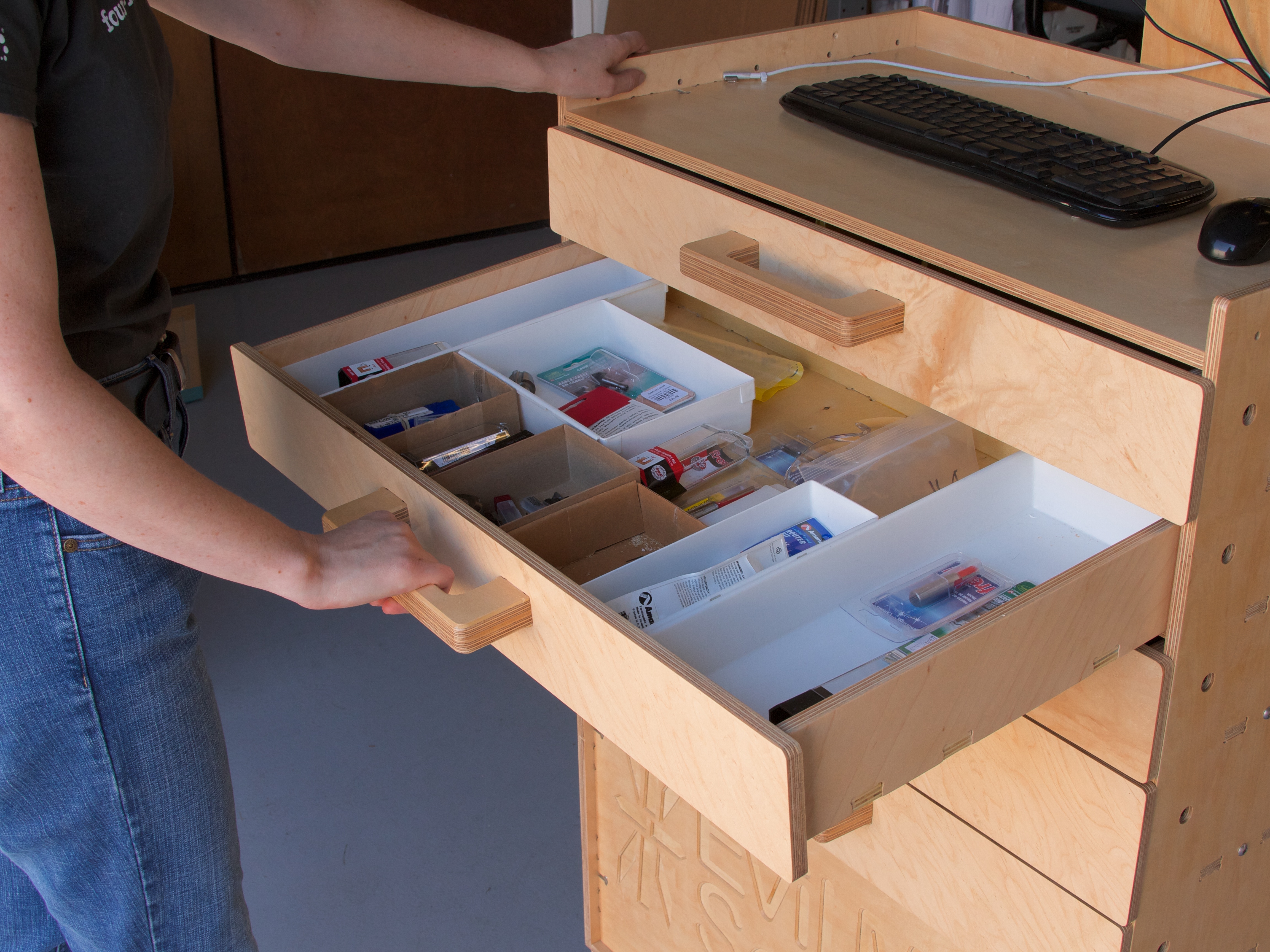
The five drawers are wide and (front-to-back) deep inside, with an interior area of 28.875 × 16.25″. The interior vertical space of the drawers is three inches, for the top three drawers, and four inches for the bottom two drawers.
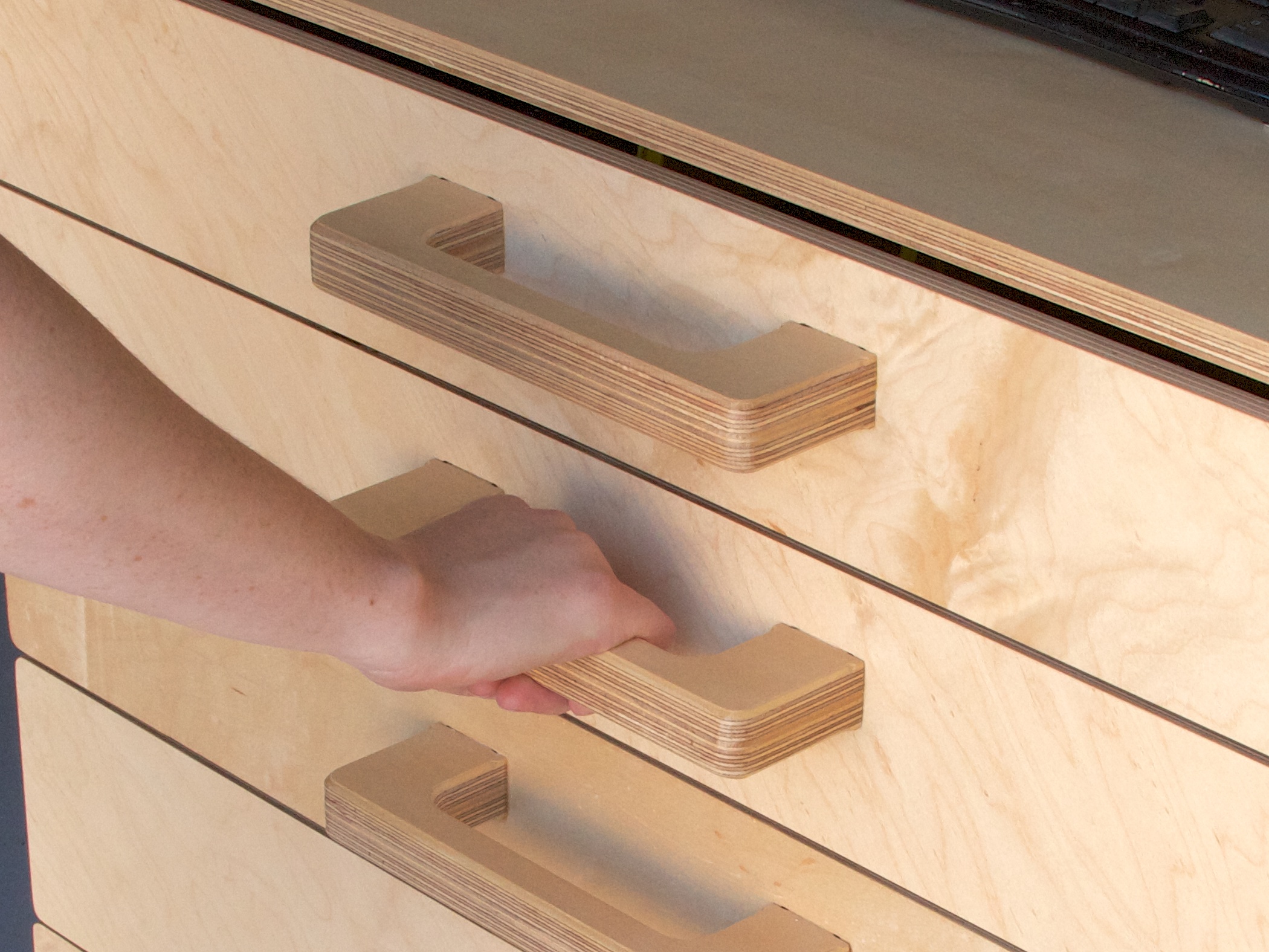
The drawer pulls are made from two layers of half-inch plywood glued together. They also have beveled edges, which we made by routing along part of their outline with a V-carving router bit. (You can also bevel them by sanding, with a little patience.)
All of the exterior surfaces of the workstation (drawers and pulls included) are finished with water-borne polyurethane varnish.
The drawers are designed so that they can easily slide in and out, but are captured to prevent them from falling out accidentally.
Our other tool chests have a mixture of plain drawers and drawers with ball bearing slides. In this case, we opted for plain rails rather than slides, in favor of simplicity, space savings, and the way that we thought it should look, feel, and sound. As the drawers are fully built from ½” plywood, they are tough enough to handle it, and the fine wood of the drawer sides is not hidden behind a metal railing. There’s only the reliable friction of wood-on-wood, not the creaking, wobbling, and clicking that you sometimes get with drawer slides. (We ourselves ooh-and-ahh over a good drawer slide now and then, but sometimes there are other good solutions, too.)
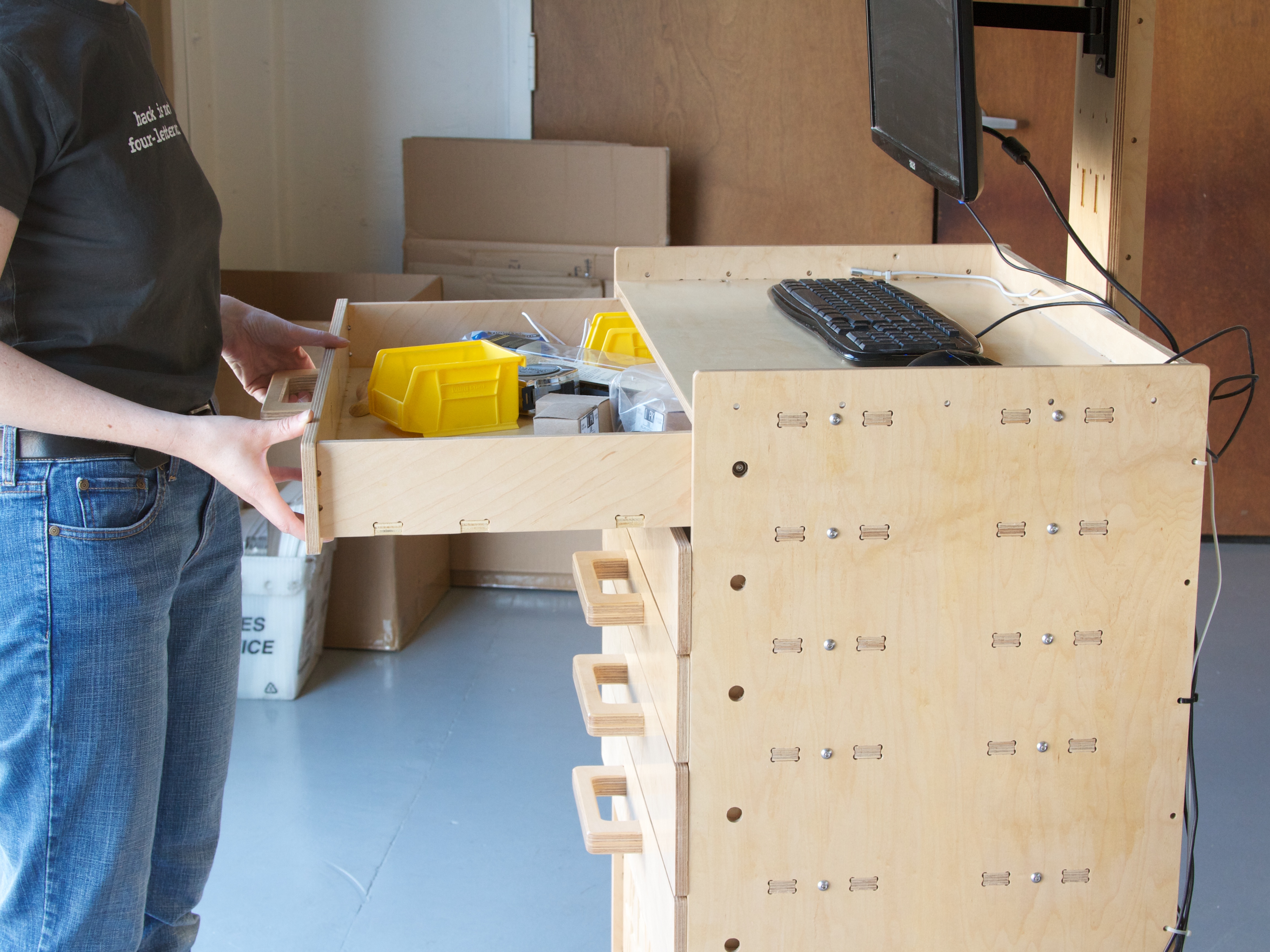
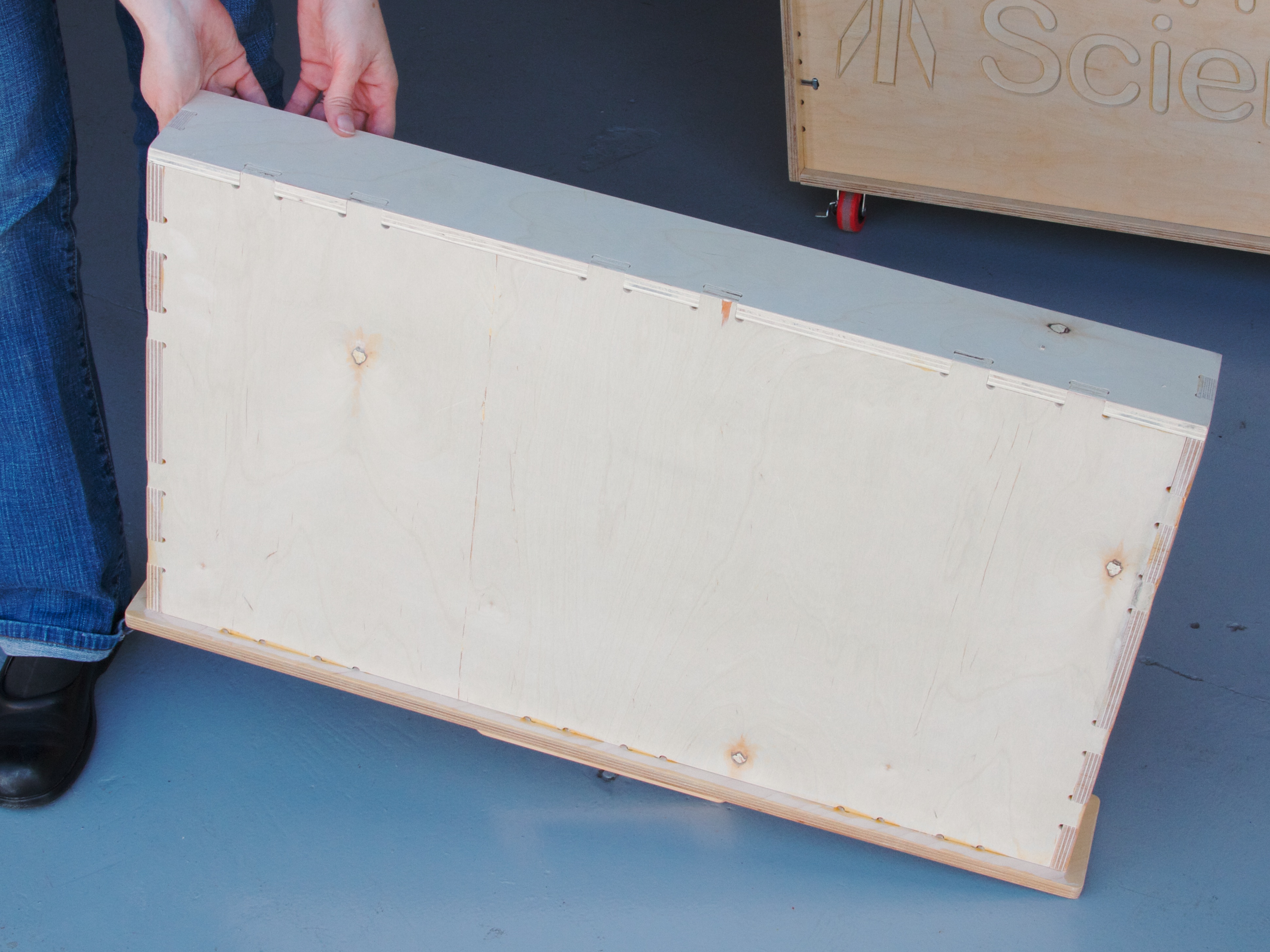
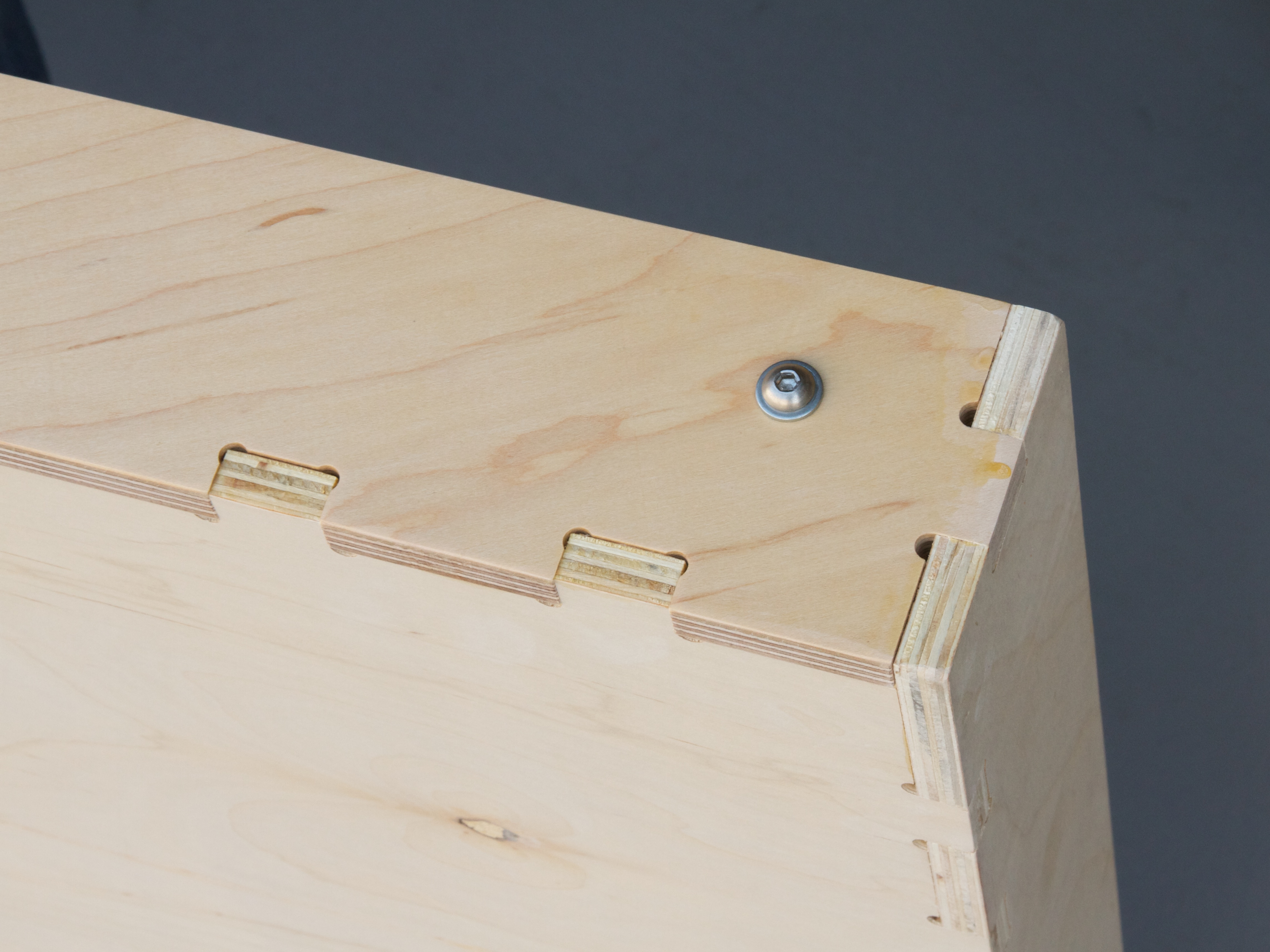
In the photo above, you can see that the top deck of the workstation is attached to the side wall by two sets of tabs through slots and two screws (the latter are more visible in subsequent pictures). Each screws is attached to a square nut in a T-slot in the top deck. Similar tabs, slots, and screws are used to hold the rails that support the drawers, as well as the bottom deck of the workstation, and a few of the other structural components. Using tabs and screws like this provides a very rigid assembly, yet allows the whole workstation to be disassembled for transportation, or to replace or modify any of the major components.
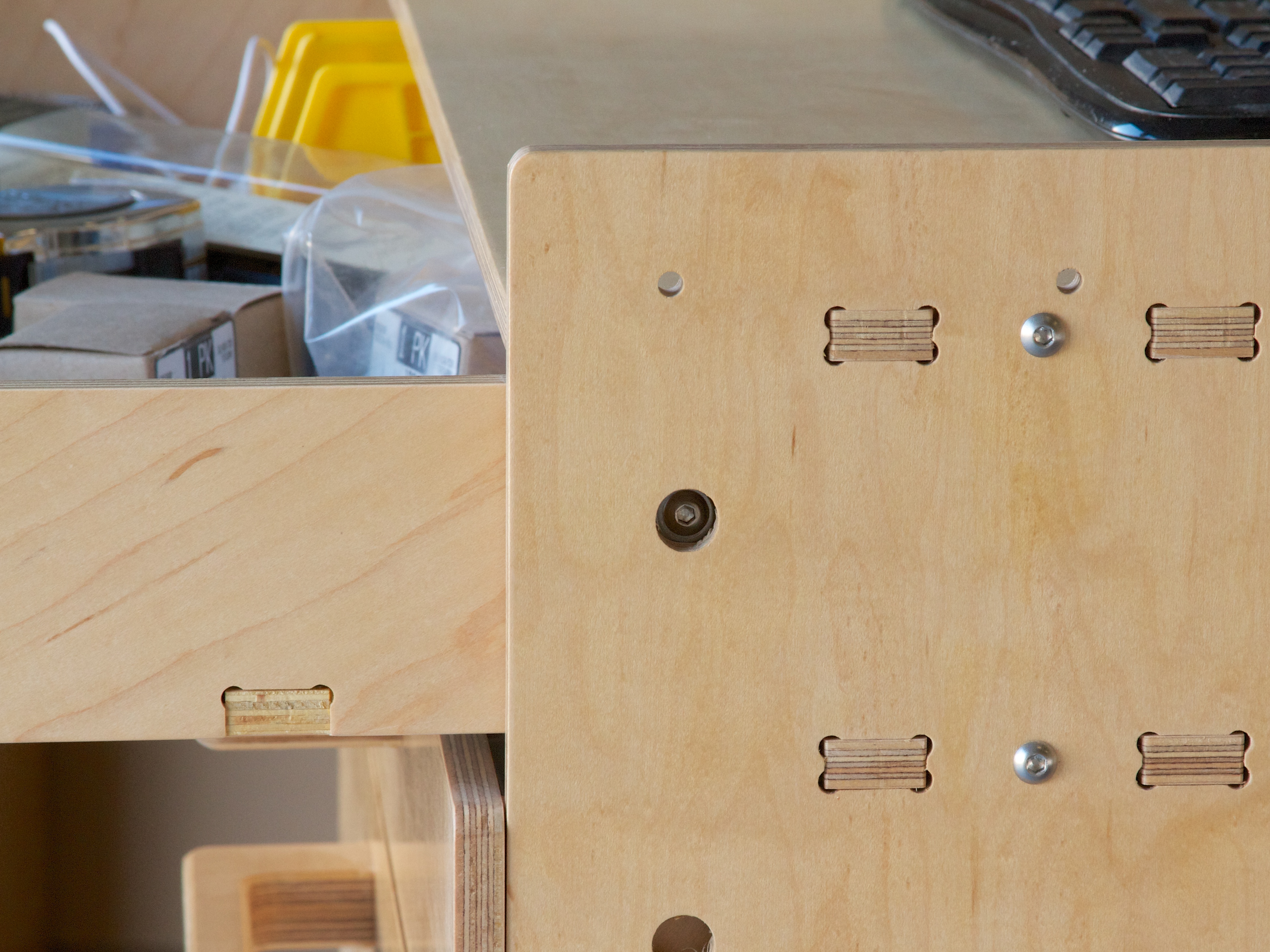
The screws that we are using are stainless steel 1/4-20 button-socket cap head screws, which give a neat, finished appearance.
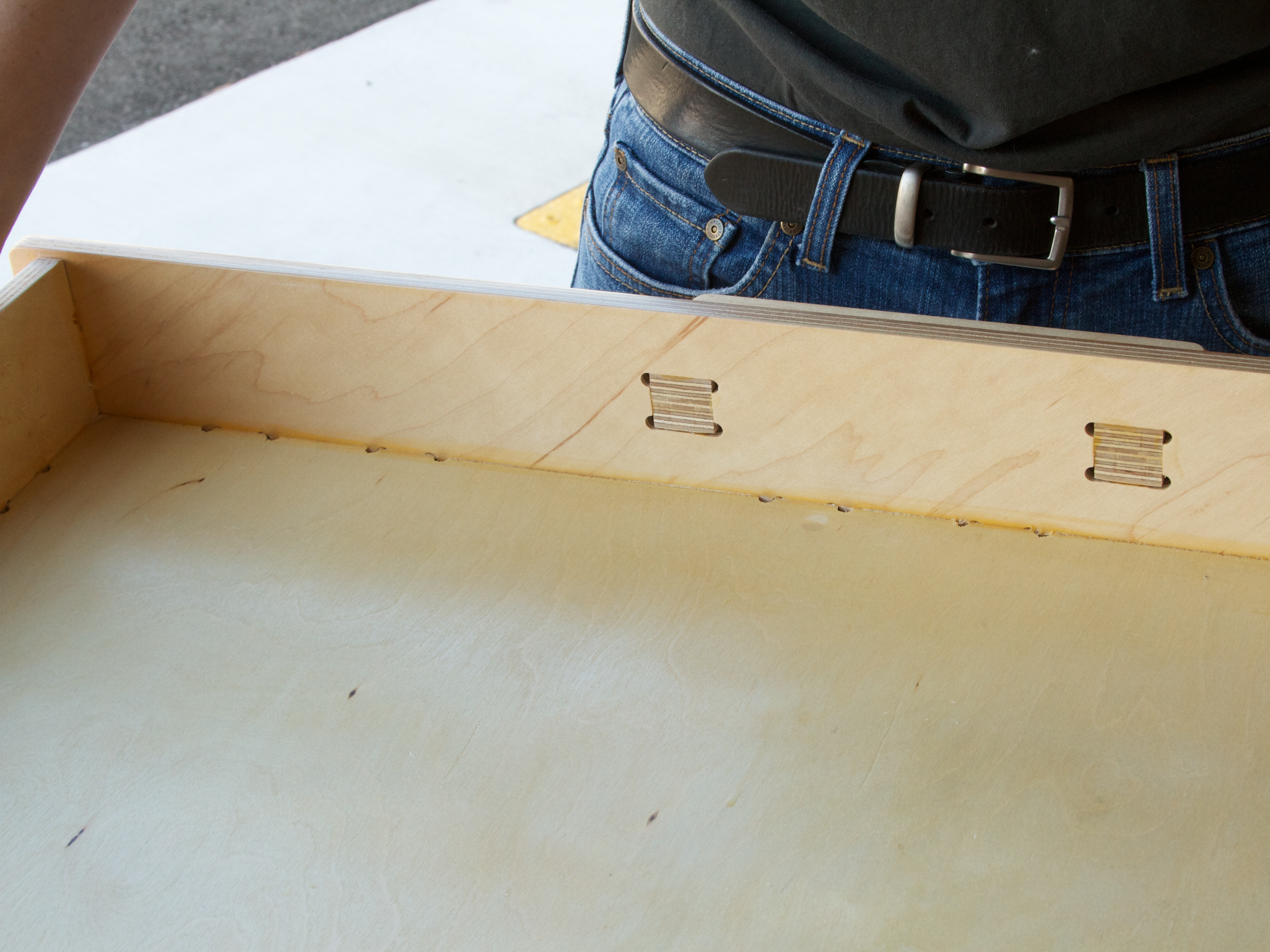
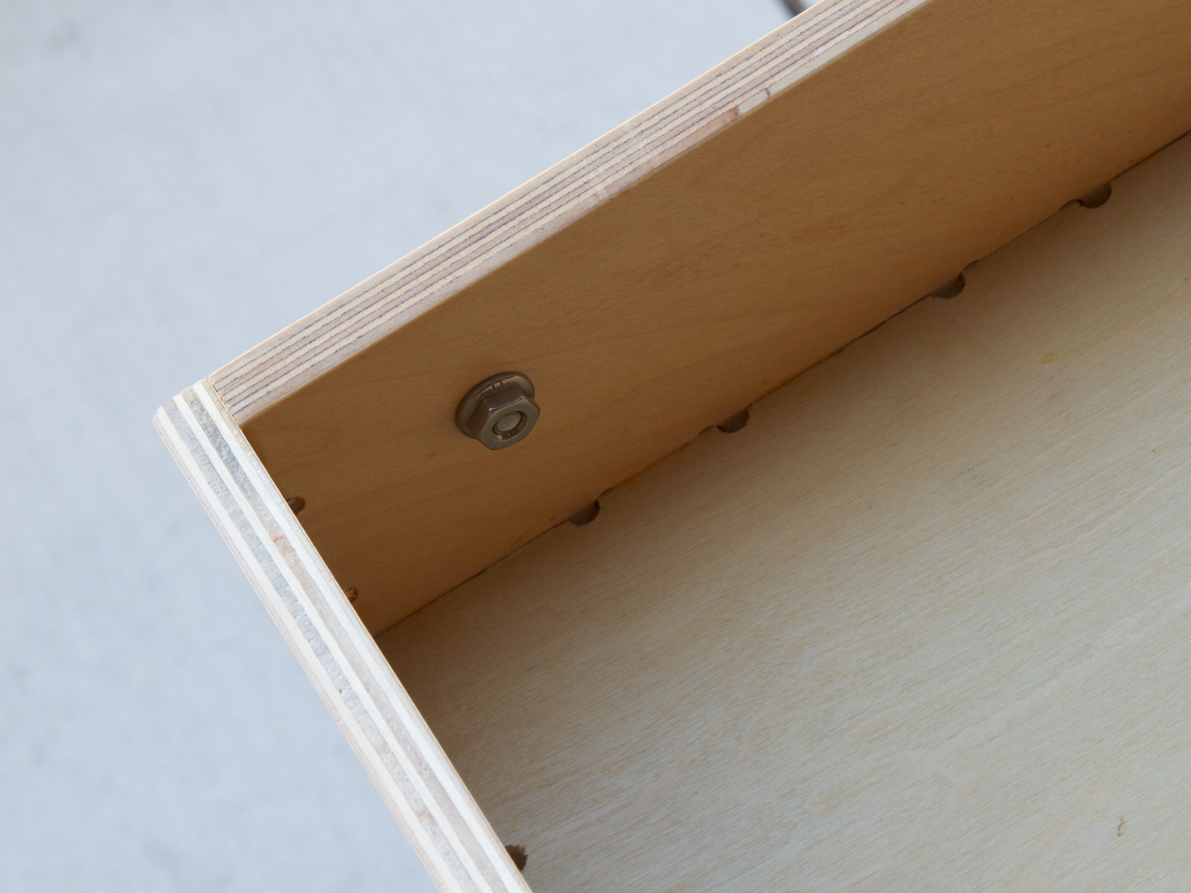
Near the front of the workstation, where each drawer sits, is a through-hole. If you look in the top of those holes, you can see one more screw head. That screw is actually attached to the side of the drawer, and slides through a groove on the interior of the workstation’s side wall. When it gets to the front of the groove— in the position shown — it acts as a stop to prevent the drawer from falling out. The through hole is provided so that you can insert or remove the screw, to lock the drawer in place or to remove it.
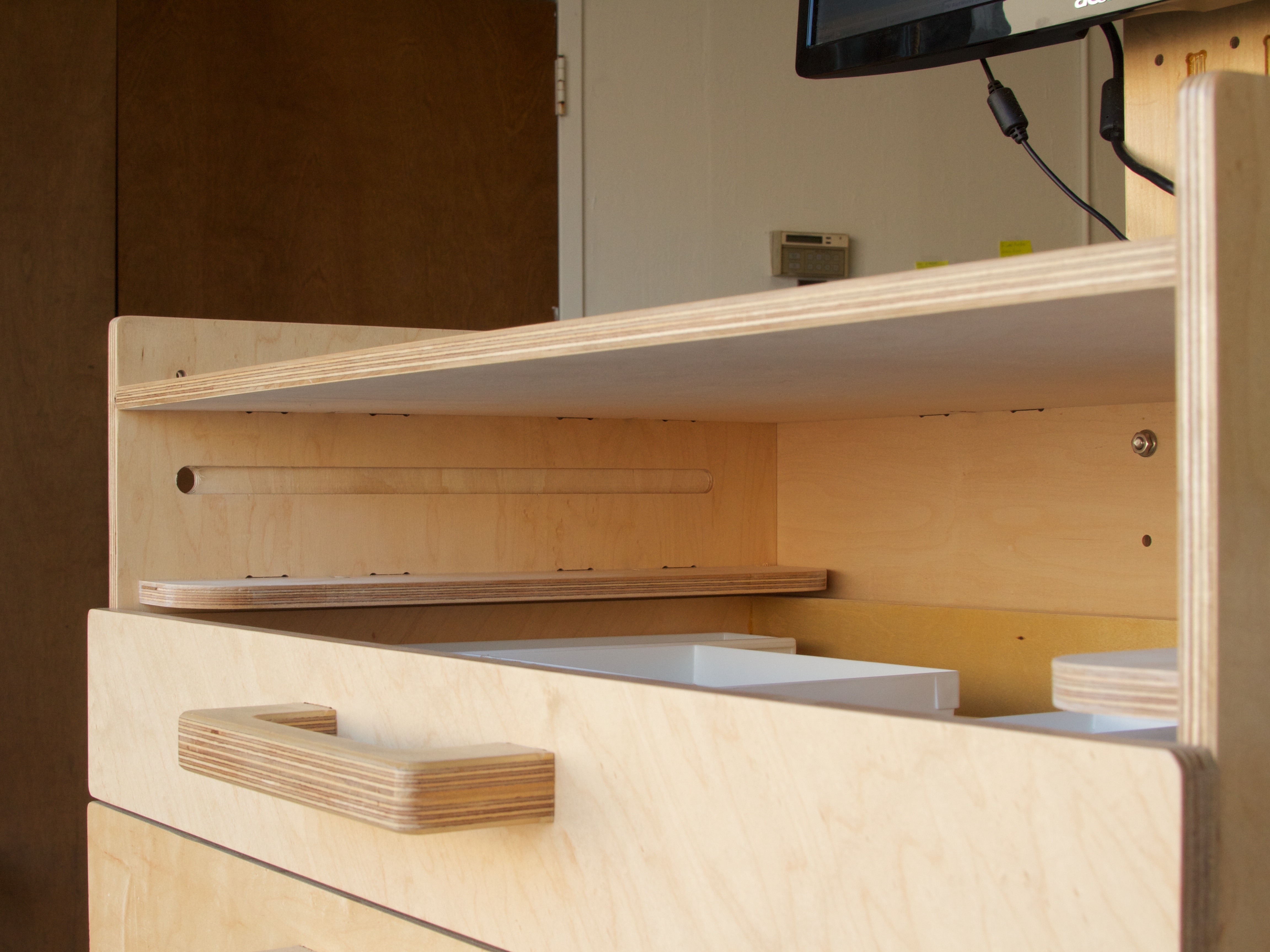
If we remove the top drawer, you can see the groove that constrains its motion. You can also see the rails that the top drawer slides on.
These small rails are used to support three of the drawers. For structural and isolation reasons, the middle drawer and bottom drawer actually have full-width platforms beneath them.
And, fully pulling out the second drawer, you can see that the rails above also prevent this drawer from tipping out.
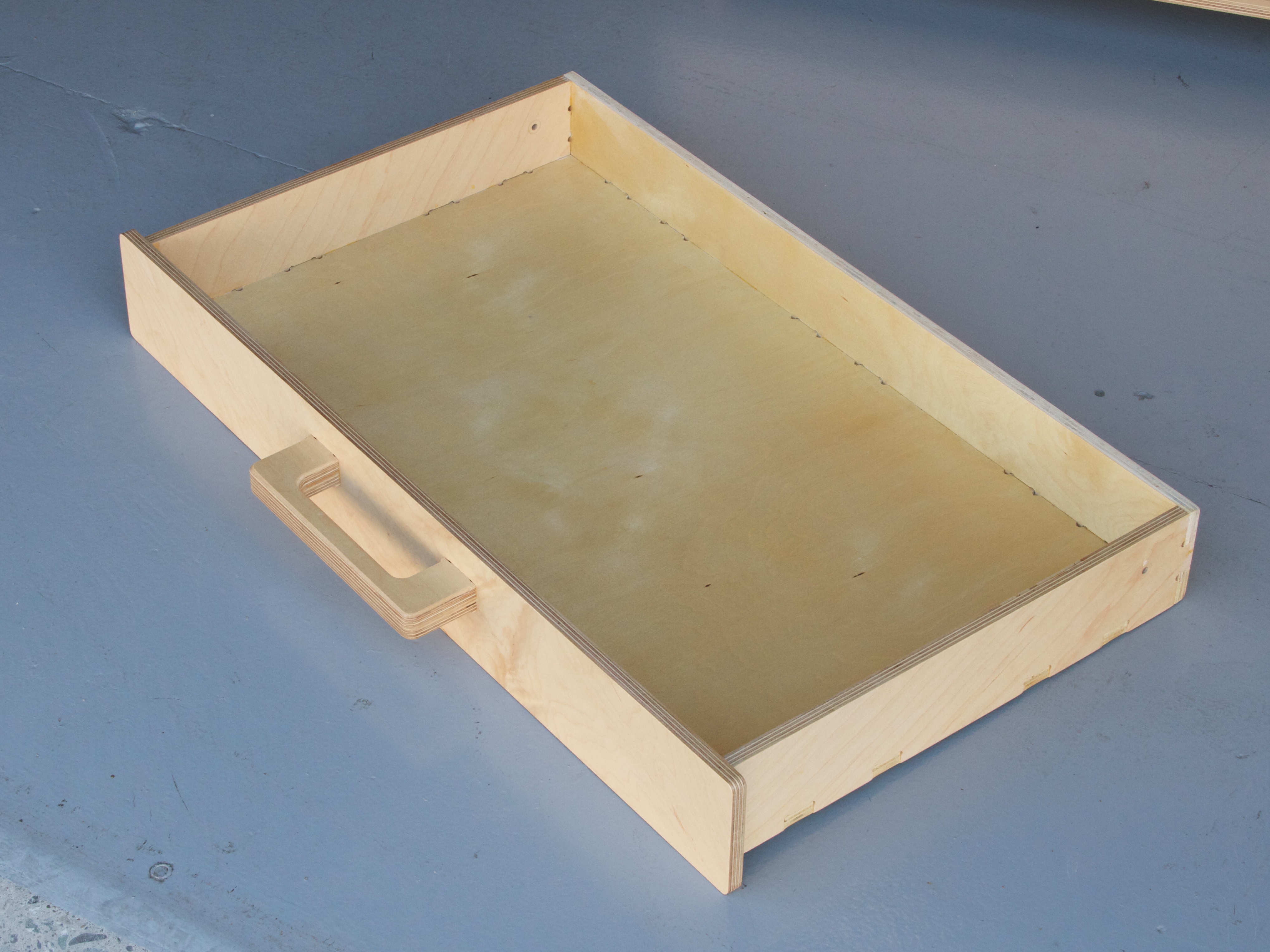
Here’s what one of the drawers looks like on its own. The front and sides are made of the same finest-grade maple-faced birch plywood as the rest of the workstation. We used a less expensive grade of 1/2″ birch plywood for the back and bottom of the drawer, which are seen less.
Each drawer is assembled with interlocking tabs and held together with wood glue. The bottom, back, and two sides are glued together first. Then this assembly, which has short, 1/4″ deep tabs sticking out towards the front, is mated and glued to the drawer front, which has a set of machined pockets (recesses) positioned to receive those tabs.
Finally, the drawer pull— again, made of two layering two 1/2″ thick cutouts —is inserted from the front of the drawer and glued in place.
The drawer stop is a short (3/4″) button-socket cap head screw though the side of the drawer, with a lock nut on the inside to keep it in place. We’ve found that adding a 1/2″ OD washer underneath the head of each screw gives more reliable performance.

Down below the drawers is the front bulkhead of the computer bay. We carved our logo into this part; you may want to leave it blank or add your own logo instead. The bulkhead is held in place by four sets of tabs and screws with T-slots on the left and right side.
Down yet further, there are four 2″ diameter red polyurethane casters: two that rotate and two that do not. Each is rated for 100 pounds, giving the full workstation a potential capacity approaching 400 pounds.
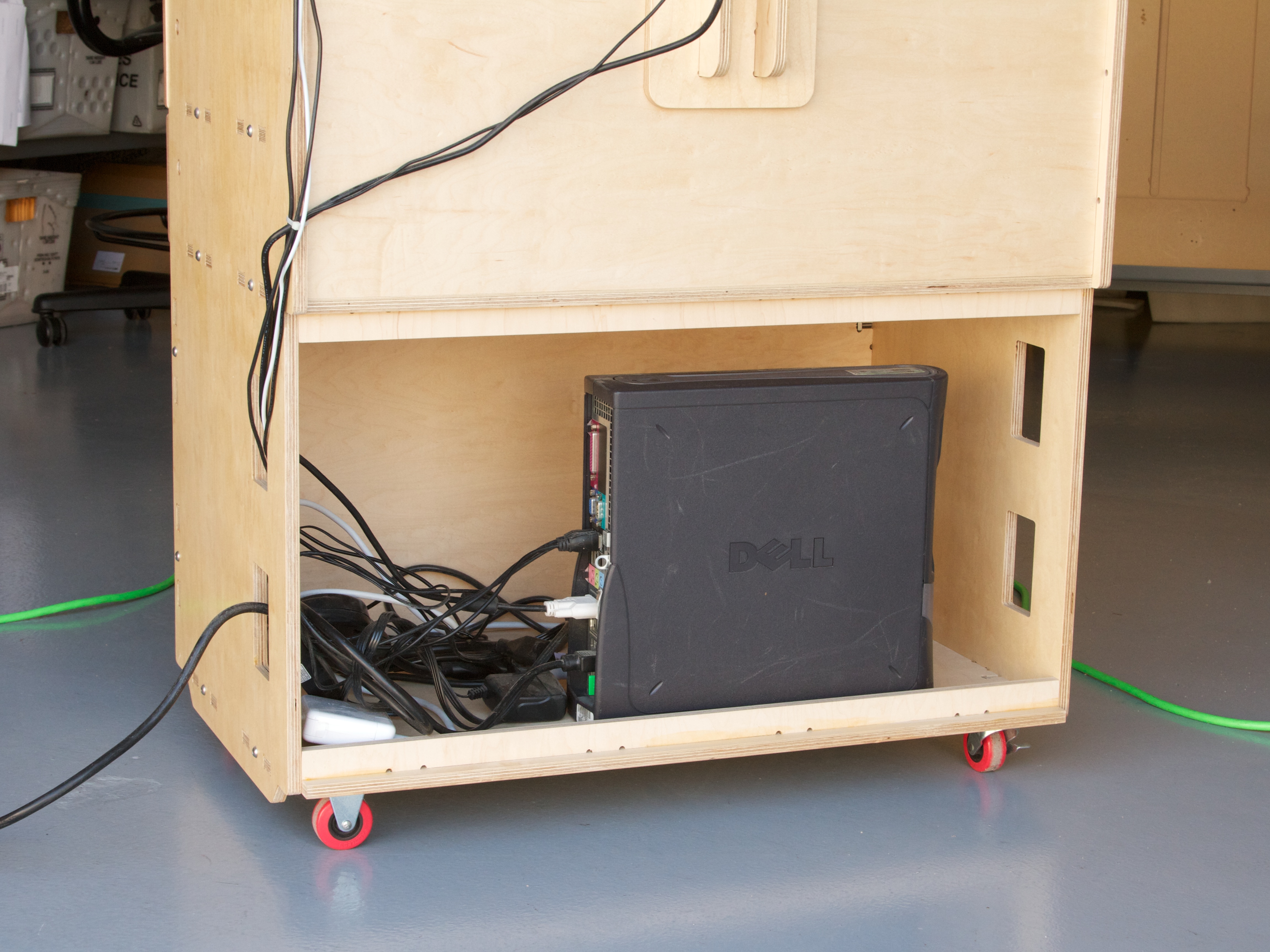
The computer bay is visible on the back side. (And, please excuse our rats nest.)
The top and bottom sides of this compartment are solid pieces of wood, rather than just rails. The casters are bolted to through the bottom face, using four sets of button socket cap screws and hex lock nuts each.
Our original intent was that this could be a dust-resistant environment for our computer, so the power and other cables are routed through side holes that can be plugged with low density foam or other filter media.
You may also notice that there is a small lip wall, 1″ high, protruding from both the floor and ceiling of the computer bay. This provides a solid surface— a ring all the way around, —that you can cap.
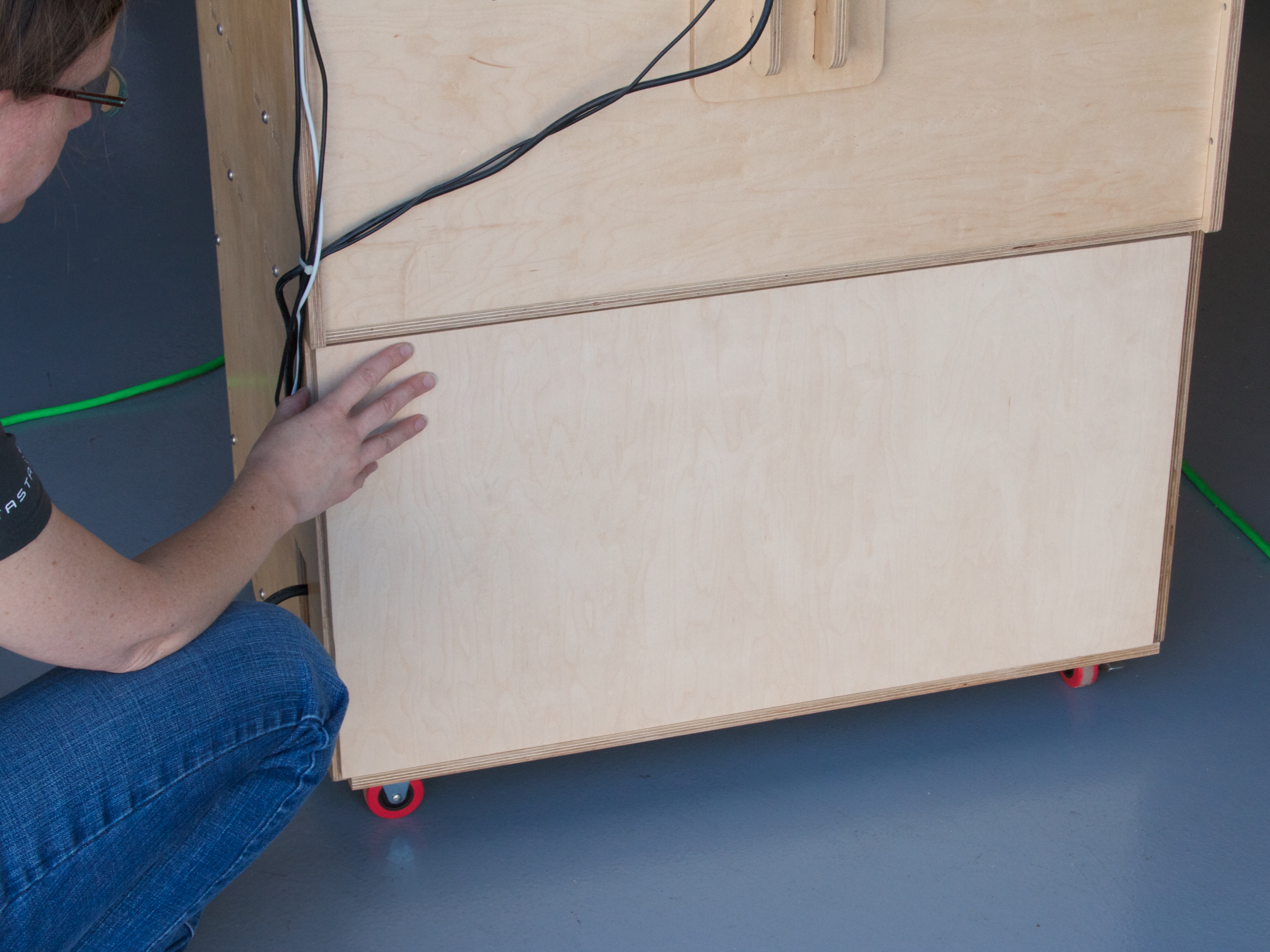
The rear cap is a rectangle of plywood, positioned where this mockup board is located. Our plans include this optional board, and two draw latches positioned on either side to hold it in place. Additionally, you may want to put a cork gasket between the two for a snug fit; we’ve called out a sticky-back 1/2″ wide cork strip in our list of parts.
Aside: Why haven’t we sealed up the computer bay on our own workstation? Turns out that dust has been much less of a problem than we thought— our dust collection system works very well —while our CNC machine’s software *ahem* requires us to hard reboot (by physically holding down the power button) on an all-too-frequent basis. As a workaround, we may attach a regular light switch fixture to the side of our workstation as a power switch at some point.
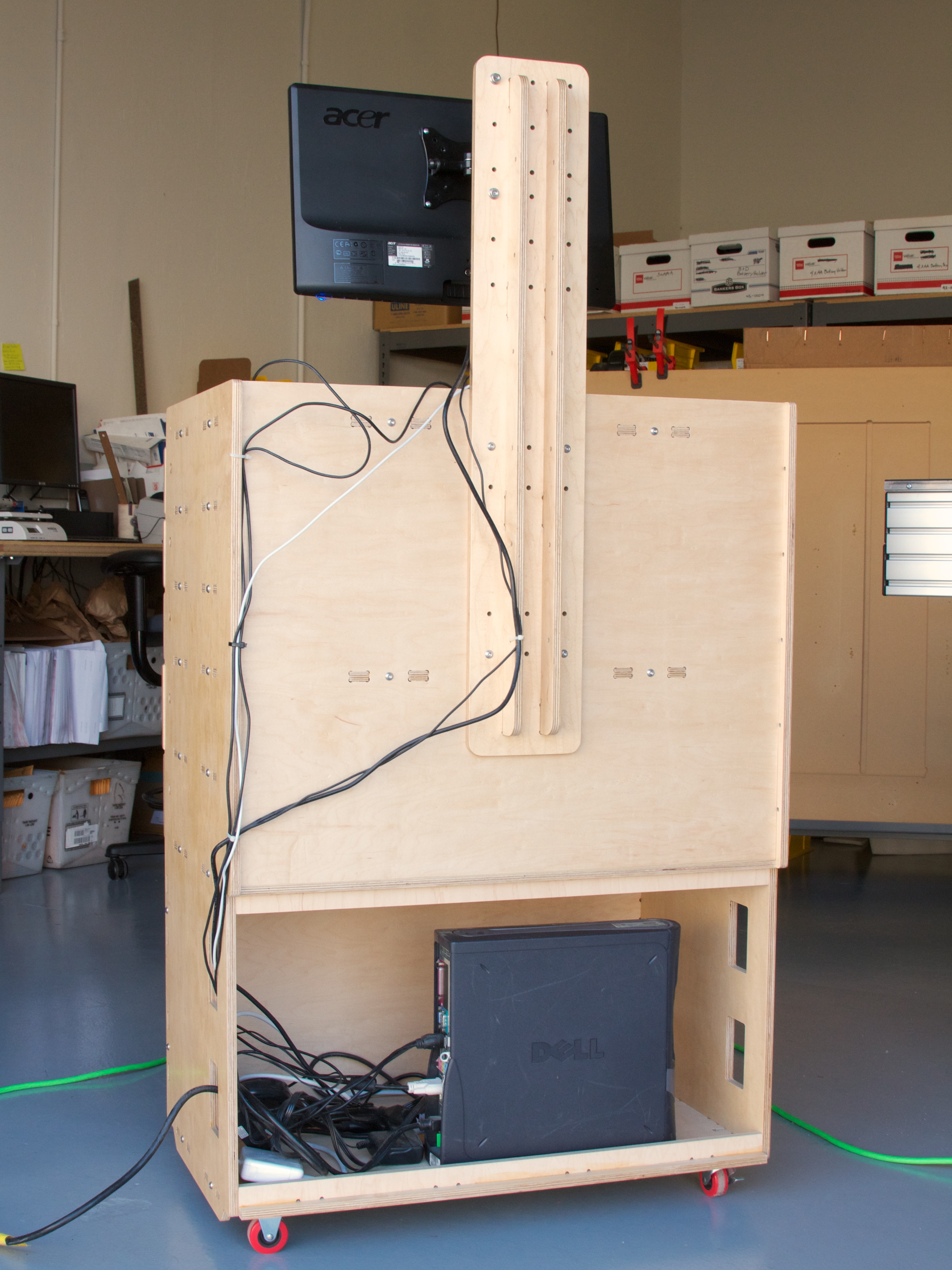
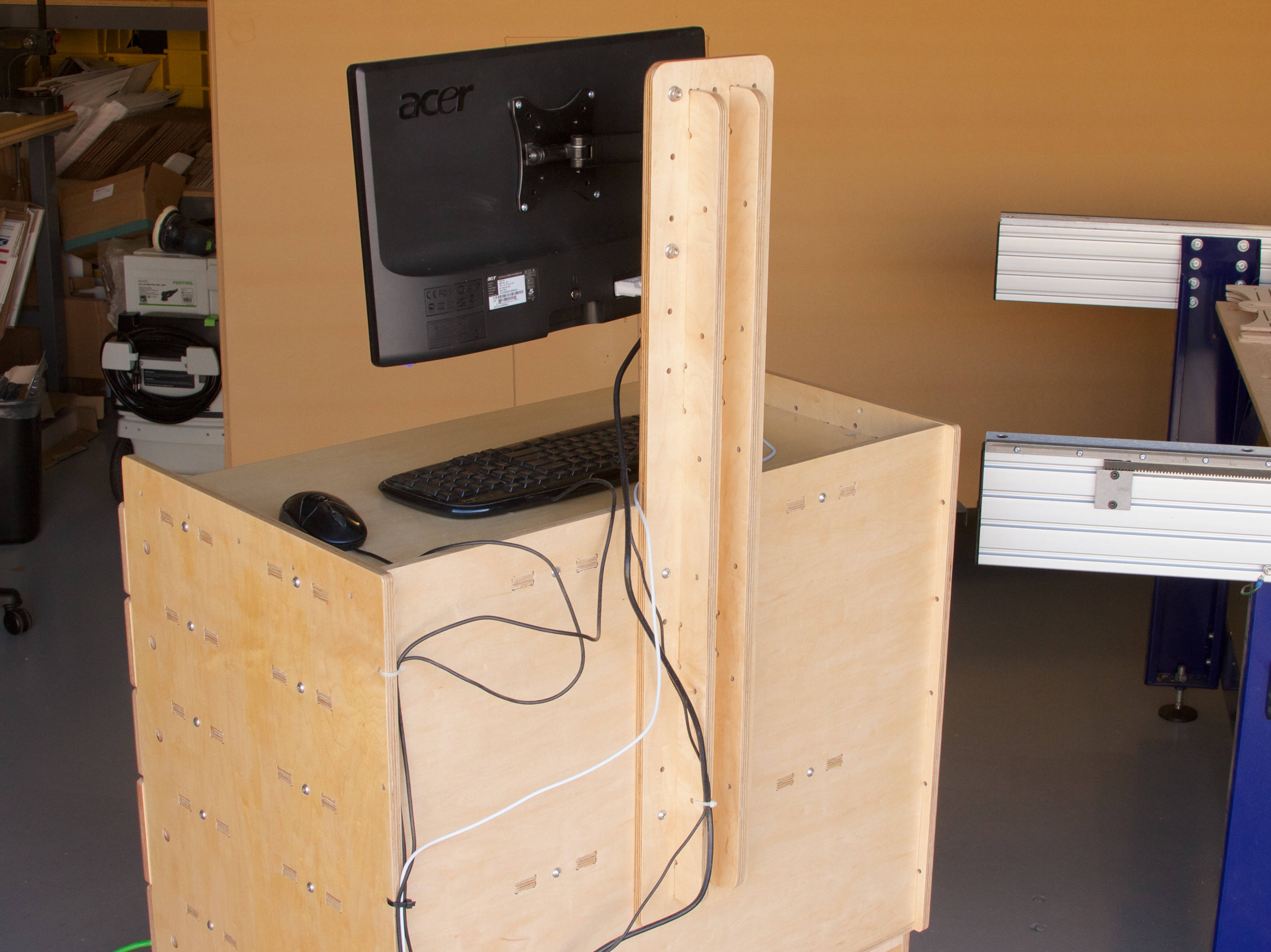
The “neck” of the workstation is bolted to its back side, using button-socket cap screws and locknuts located behind the drawers. The neck consists of three pieces of wood: a flat piece with mounting points for the VESA monitor mount and two stiffening ribs, glued into it.
From the back, you can see that the top deck and the platform supporting the middle drawer are anchored by tabs that stick into the back face of the workstation.
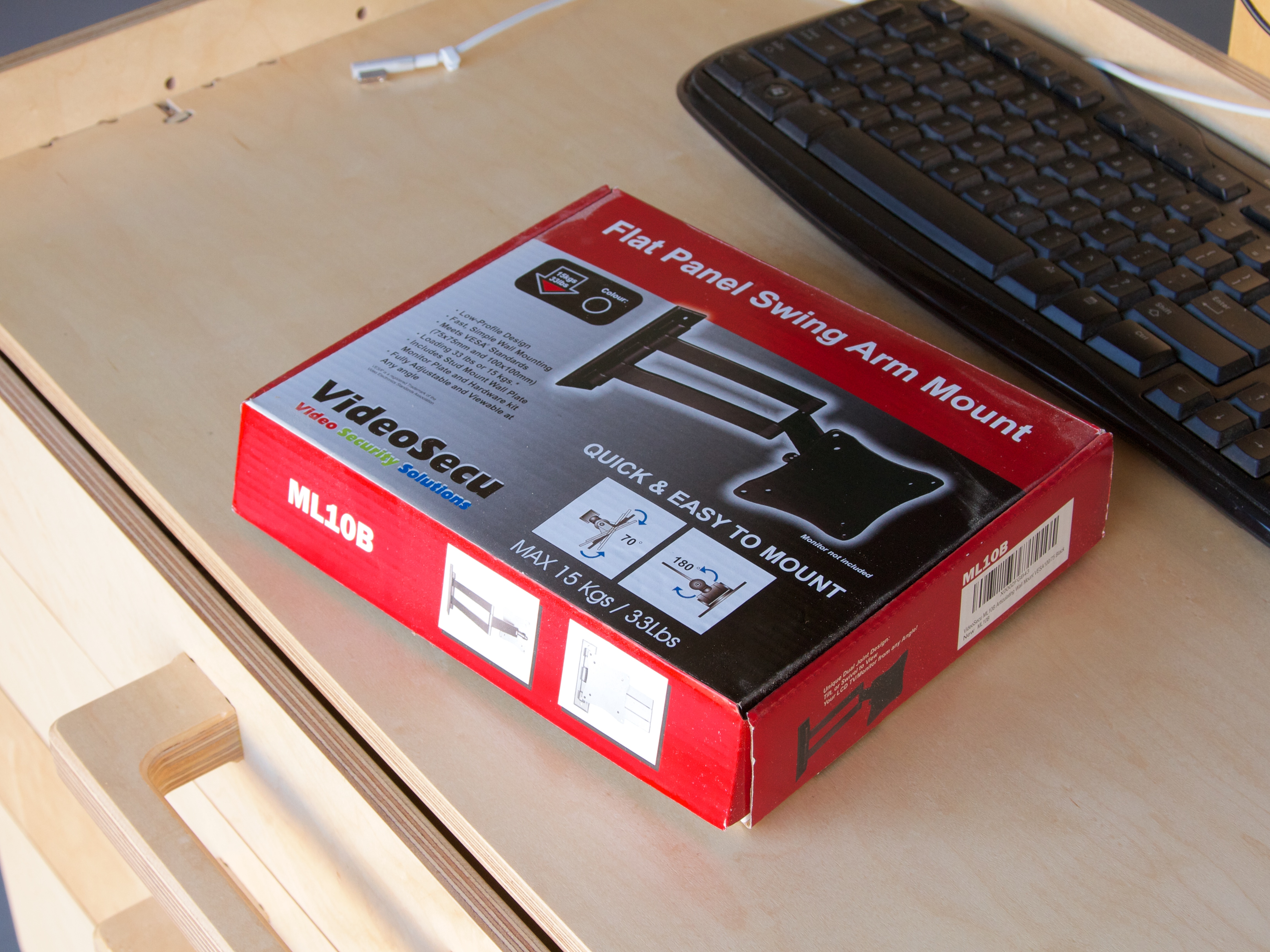
Our computer’s monitor is an inexpensive LCD with a VESA mount that is revealed once you remove its built-in stand. For the VESA bracket, we found the VideoSecu ML10B (compact, low in cost, and reasonably well made) to be a good option and designed the “neck” of the workstation with hole spacings for it.
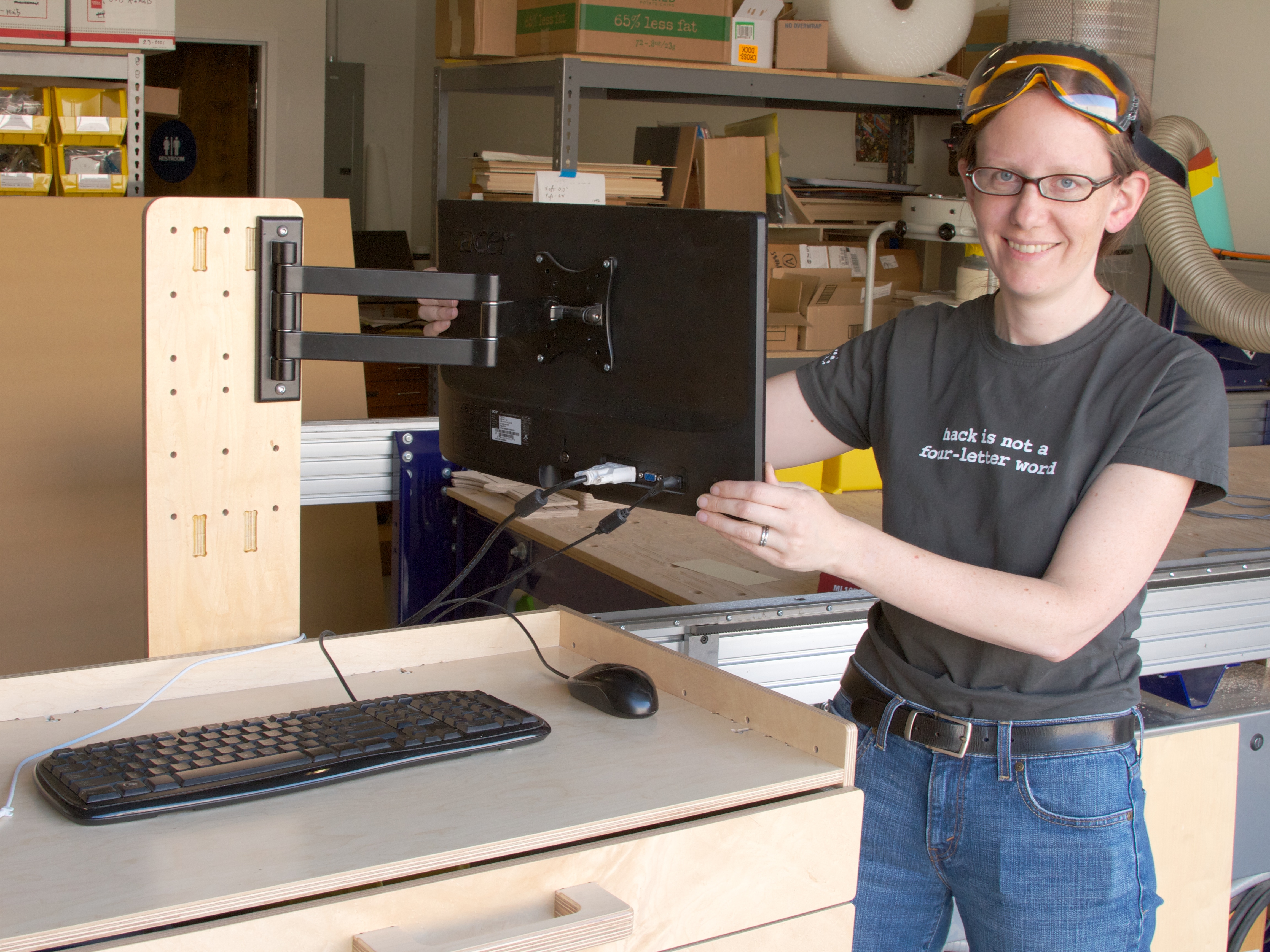
For the monitor to be exactly centered when retracted, the rear base (wall-mount part) of the VESA bracket needs to be offset sightly from center. Our design has two sets of offset holes of the correct spacing (in case you need it to swing left instead of right) and three possible mounting heights.
The two mounting holes in the rear base of the ML10B are a bit under 1/4″, so won’t automatically fit the same screws that we’re using elsewhere. You can use smaller diameter screws (and accept a little bit of slop in where it mounts to the neck), but it turns out that you can simply enlarge those holes with a regular 1/4″ diameter drill, and then mount it without any slop. The base is made of soft cast aluminum that drills out easily, and there appear to be no structural or other downsides to this modification.
Design Files:
We designed the workstation in Inkscape, to be CNC cut from 1/2″ plywood, requiring only a 1/4″ router bit. These files contain the outlines to cut, fabrication notes, as well as a legend for which part is which:
- Download PDF version
- Download Inkscape SVG version
Parts Required:
- Plywood, 1/2″ thick, approx. three 4×8′ sheets. Higher quality is better.
- Wood glue.
- VESA monitor mount. VideoSecu ML10B as described above recommended.
- Water-borne polyurethane varnish, brushes, sandpaper (suggested).
Additional hardware, all the little bits:
| Line | Qty | Description | McMaster Part # |
|---|---|---|---|
| 1 | 2 | Swivel Caster with wheel brake | 78155T62 (each) |
| 2 | 2 | Rigid Caster | 78155T63 (each) |
| 3 | 26 | 1/4″-20 x 3/4″ Screw (casters, drawers) | 92949A540 (pkg of 50) |
| 4 | 42 | 1/4″-20 x 1 1/4″ Screw (monitor mount, t-slots) | 92949A544 (pkg of 25) |
| 5 | 32 | 1/4″-20 Locknut (casters, drawers, monitor mount) | 97858A100 (pkg of 25) |
| 6 | 36 | 1/4″-20 Square nut (t-slots) | 94855A247 (pkg of 100) |
| 7 | 10 | Flat Washer (drawers) | 91525A117 (pkg of 100) |
| 8 | 1 | 5/32” Ball end hex driver (suggested) | 5497A29 (each) |
| 9 | 2 | Latches (optional) | 6139A27 (each) |
| 10 | 1 | 1/2” Cork Strip (optional) | 93305K61 (50′) |
Sourcing Notes:
- Part numbers are from McMaster-Carr, http://www.mcmaster.com/
- Latches do not include mounting hardware, 4 #6 ×1/2″ wood screws per latch.
- You are welcome to use cheaper mounting hardware. We like stainless. :)
And finally, an erratum: We’ve made one change to the design since fabricating our own. As you can see in the picture above, the front of our top deck is flush with the sides of the workstation, not with the front of the top drawer. In our design files, we’ve updated it such that the top deck now extends another half inch forward (with rounded corners), so that it’s flush with the front of the drawers, and does not leave any gap. And, since it’s all put together with screws, we plan to fabricate one and replace our own top deck one of these days.
And there you have it. We’re releasing this design under the CC-BY license, strictly as-is, under the hope that it will be useful. If you build your own, or have made improvements, we’d love to hear about it.
Makes me want to take pictures of the stand my computer is sitting on. My father built it for a wide-carriage dot-matrix printer, and it’s held together by screws: two legs, the bottom shelf, the top deck, the brackets holding the paper guides (two pieces of 1-inch PVC), and a slide-out shelf to catch the paper as it comes out. (His computer stand was made with double-sided shelf standards on feet, with shelves of various sizes.)
VERY nice. I can see combining this with some of the ideas in Ron Paulk‘s mobile woodshop (http://blog.makezine.com/2012/08/20/mobile-woodshop) … especially with the drawers, and slots for hand tools, to build out my personal workshop.
Trick with the EMSL setup is I need to the shop to build the CNC rig to build the shop! Damn You GodelEscherBach! Gotta do the first round old school.
Is the PDF file empty? I can’t open it… many thanks for this nice idea
File was looking strange in some PDF readers; I’ve fixed the issue and uploaded a new version.
Fixed – thanks!
So, I have to ask. Which CNC system are you using. Your products are so well designed I figure you’ve chosen your CNC machine with much care.
Thanks! We spent a lot of time researching which system to get, comparing dozens of models from dozens of manufacturers. In the end, we made what we thought was an excellent choice. But, having built and used it, we’d be very likely to get a different brand if we had to do it all over again. There are a lot of little reasons (for one, the hard reboots mentioned above) that we prefer not to recommend (nor to publicly shame) the system that we ended up getting.
Absolutely amazing, Could you fit a nice cheap 20mm skate bearing into that hole instead of your current stop? These VXB skate bearings cost less than 50 cents each.
http://www.vxb.com/Merchant2/merchant.mvc?
Sorry bad link,
http://www.vxb.com/page/bearings/PROD/SB/Kit7339
You could fit a bearing (but not that one, unless you resize the groove), however there isn’t any real advantage to using a bearing versus just a washer.
A couple of things to consider:
– Any inexpensive bearing will always gradually leak out grease that will gradually degrade the wood. Yes, you can get *all* of the grease out by a long soak in acetone or an industrial cleaner/degreaser, but then it rusts pretty quickly. Another alternative would be to heavily varnish the groove to make it grease-resistant, but that’s difficult to do well, and the varnish will still wear down when the bearing rubs on it. Ceramic bearings don’t leak grease– and might make a great choice –but sure aren’t 50 cents each.
– If you’re just using the bearing as a stop, it needs to have a diameter of roughly 3/8 – 1/2″, and an overall thickness (on the outside of the drawer) of about 1/4″. That 1/4″ needs to include (A) a washer that keeps the inner ring separated from the drawer side and (B) whatever screw is used to hold the bearing in place. This means that you need to use a pretty thin bearing, likely well outside of the “cheap” types.
– My guess is that you want to take advantage of a bearing to make the drawer slide more smoothly. But simply using a bearing as a stop, as opposed to just a rounded screw head, doesn’t really accomplish this. (The back of the drawer does not currently rest on the screw head– it is vertically centered in the groove, with ample clearance so that it does not touch the top or bottom.) All that it would change would be to give you a slightly harder stop.
-If we moved the screw’s mounting point down, such that back end of the drawer rolled on the bearing, that would allow it to roll neatly *if* you lift the handle while you drag it, but there would still be friction from the front side of the drawer. I think that it would feel pretty weird to have a drawer that exhibits decent friction when you pull straight, but rolls (perhaps unexpectedly) when you lift the handle. If you fixed this, by using two sets of bearings, one near the front, one near the back, you’d limit the travel, so you’re probably better off just using standard drawer slides.
And as for VXB, we’re already happy customers of theirs in other contexts. :)
I’m really curious what tools, extensions, tips and tricks you guys used in order to actually do this design inside Inkscape? I love inkscape, and I use it a lot for laser cutting stuff, but I’ve found that it’s NOT a CAD program and is very limited when it comes to CAD-type roles. I do get by, but I can’t imagine doing the design for such a large project in inkscape and getting all of the tabs and slots the same sizes, etc.
This is an excellent question; one that might address in an upcoming blog post.
More or less, we just use Inkscape and the built in tools, with a few reliable tricks. We could always spend $7-10k on a nice CAD package that would do everything efficiently, but there’s a sense in which that isn’t any better.
Just a friendly “me too”. As someone who uses Inkscape for all his lasercutting / CNC milling, I’d love to see how others do it as well.
I keep thinking that Inkscape needs a nice set of CNC-focused tools, such as things like BoxMaker and the gear generator. In particular, I’d love to see a nice joint maker that could make a pair of slots / tabs that fit well together (perhaps with a screw hole / bolt hole like what you used in this project).
Perhaps I’ll get this ball rolling and porting BoxMaker to Python…
Actually, someone’s already done it: http://www.keppel.demon.co.uk/111000/111000.html
Maybe a compilation suite would be in order, then. Find all the existing CNC tools and package them nicely.
You guys should check out DraftSight. While it’s not open-source, it is free, and made available by a large company (Dassault Systemes, makers of SolidWorks). It’s a very nice 2D and light-3D CAD program, and it’s free! A few members of our hackerspace are using it to do some designs, for CNC and laser cutter designs, and even rocketry!
Regarding the erratum:
I’d bring the front edge of the top forward flush with the drawer front, as you mentioned, but then also add ‘ears’ bringing it out flush with the sides.
or
leave the top as-is, and make the top drawer front taller to bring it flush with the top.
We did consider the first option, but it suddenly looked less elegant, and more kludgy.
The second option is not so good; it loses the nice contiguous top surface that your hands can rest upon.
A third thing that you could do is to make the two side walls protrude a little further forward up top, so that they’re flush with the front of the newly extended top deck.
Looks great! Do you have a ballpark on total cost of materials including wood? I’m trying to gather interest in making one of these at our hackerspace.
Apologies if I missed this in the post or comments when I read this late last night.
We used two sheets of ApplePly ($110 each) and one sheet of american birch plywood (~$70). So the wood cost is about $300. Obviously, you can use cheaper grades as well, at some cost of final fit, finish, and stiffness. The VESA bracket was $15, and the rest of the hardware is about $80. We also spent about $30 on varnish, brushes, and sandpaper.
I can’t bring the files into ShopBot’s Software. Could it be available in a dxf file?
Open the Inkscape SVG file, and save the relevant portion as a .eps file; it will work. DXF does not work nearly as well.
For some reason the inkscape file will not open, and i use dxf’s all the time, with no problems
I meant, open the Inkscape file– from within Inkscape –and save the relevant portion as an EPS file. That will import nicely into the shopbot software.
(Inkscape’s DXF export performs poorly, and we would not recommend that route.)
A solid design, I wish my desk was that well built.
How are the thermals with the PC section closed up? Any reason to make the vents standard PC fans sizes, say 120mm round?
On a related note, how has your Dell Optiplex GX 270 not died it’s typical blow-every-capacitor-in-the-VRM-section death? We had a dozen of them go down that way.Then again, maybe you recaped it.
As we mentioned above, the back was never closed up, so we don’t have any data on that.
Our intention was to seal the cable routing holes with foam against dust–they weren’t meant as vents per se. You could certainly add vents or modify the size of the cable holes to suit your needs.
The computer is okay so far.
Ah, okay. I wasn’t sure if there had been any tests with the board in place, and tend to fixate on the PC side of furniture.
Continued success with the Dell!
Great !!
I will also mill that next days. Nice work.
A little beeswax on the contact surfaces of the drawers and rails will give a nice, smooth feel, and a little protection to the wood edges.
I’m beginner, so I need more info. :D
Is it possible to include a dxf format of the drawings? I can not access PDF because my stuff things it is a bitmap and I can not use svg files.
Thanks
Wondering on the layout file, where do you have it running the bit on the line?
Inside, Outside or Centered on the cut line?
Thanks
Bit runs outside the line. You may want to run a couple of smaller test parts first, to make sure that your kerf is appropriate, and add a small adjustment (+ or -) to your effective bit size if it is not.
Thanks, I plan on using the plans the way you have them described with 1/4″ bit.
Looks like a great project.
I assume the holes are inside or are they outside too?
The holes are “inside” That is, a hole that looks like a 1/4″ hole really is a 1/4″ hole.
I tried importing the .pdf into Rhino and get an error, “Error reading file CNCWorkstation1.0.pdf — Invalid PDF.”
Anyone else have luck opening in Rhino?
Maybe I’ll download Inkscape for now and take it for a spin…
-dave
ps. LOVE this design, and that you’re sharing it. Our hackerspace is going to build one on our CNC router, for our CNC router!
We have not seen that error, but then again, we don’t have Rhino. I’d suggest exporting it as eps or PS directly from Inkscape, and importing one of those into Rhino.
Thanks. I used Inkscape to go from .pdf to .dwg (or was it .dxf …) and could import it into Rhino and CamBam.
Tomorrow several of us are meeting at http://www.collexion.net to build one of these for our CNC router. This is one of our first big projects on the router. Wish us luck!
-dave