


Some time ago, we wrote up a tutorial about using an ADXL330 accelerometer with an AVR microcontroller. A couple of years have passed, and so we’ve returned to update and clean up some loose ends on this project.
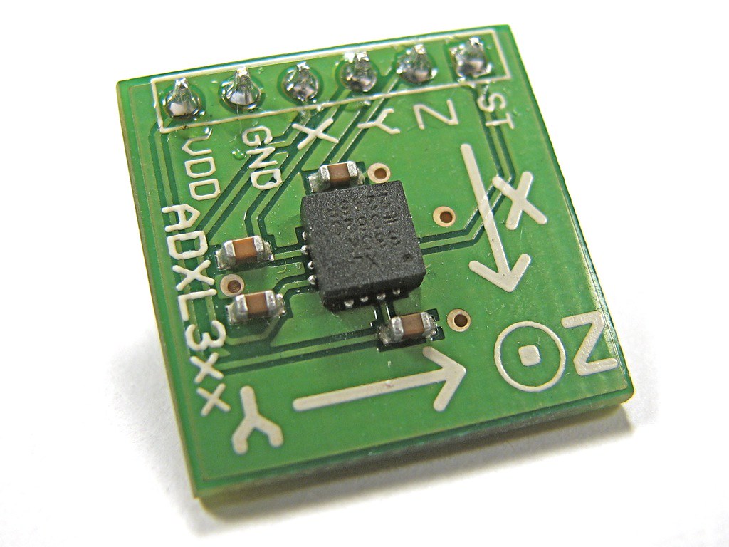
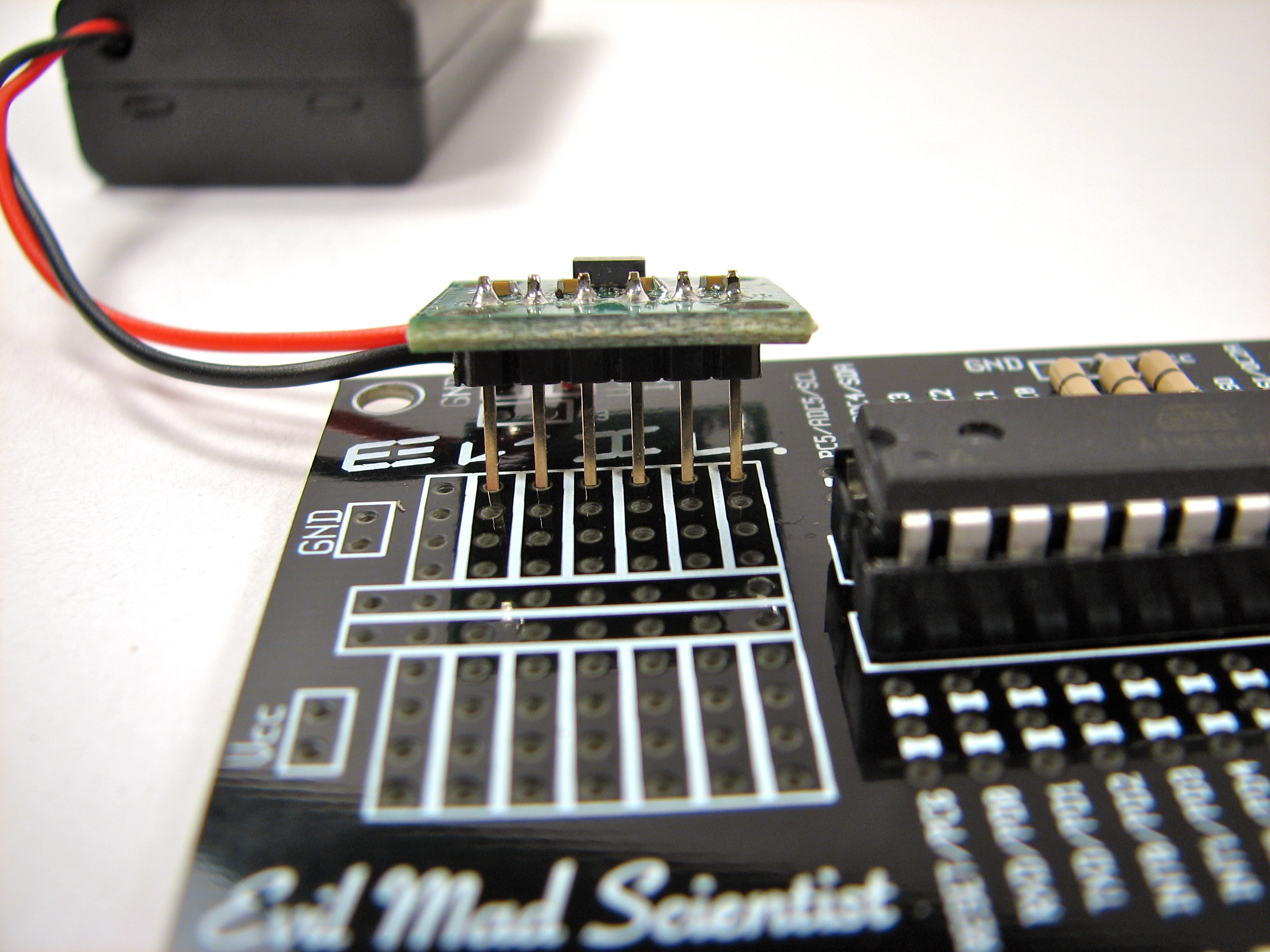
The Analog Devices ADXL330 that we originally wrote about (shown above) was one of the original low-cost breakthrough devices– the ones that first showed up in Wii controllers and other consumer electronics with accelerometers. At the time it cost $11.50 in unit quantity, and we were able to get one pre-soldered to a breakout board at Sparkfun.com for $35.
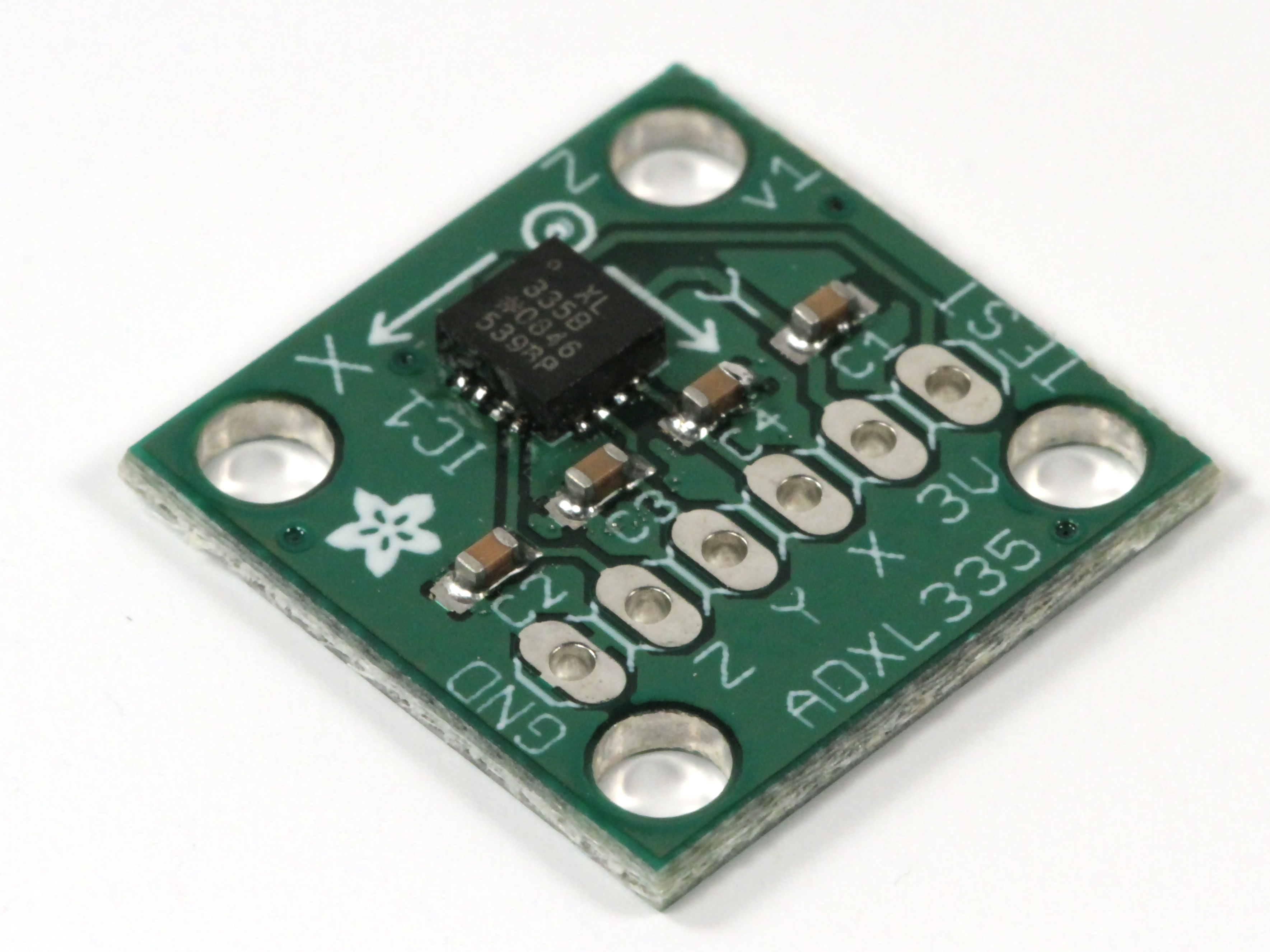
In the time that has passed, the ADXL335 has come along as a next-generation drop-in replacement for the ADXL330, which now bears the dreaded stain of “not recommended for new designs.” (The ADXL335 is less expensive than the 330– currently $5.42 each, compared to $12.15 for the 330 –but is otherwise mostly equivalent.)
Tiny chips like these are (IMHO) not easy to solder, so it’s convenient that this new chip is also available presoldered to a breakout board. We’re using the one from Adafruit ($20), but similar pin-compatible boards are also made by Analog devices (model EVAL-ADXL335Z) and Digi-Key (model DKSB1002A). (Sparkfun also has a ADXL335 breakout, but it’s pin-compatible to their discontinued ADXL330 board, not to these others.)
Besides bumping up to the current accelerometer chip, we’ve also cleaned up the project a little bit with one of our ATmegaxx8 breakout boards. Not that there’s any magic hidden in that board– you certainly can still do this project on a breadboard –but at our presentation is a bit neater, and the end product is much more reliable.
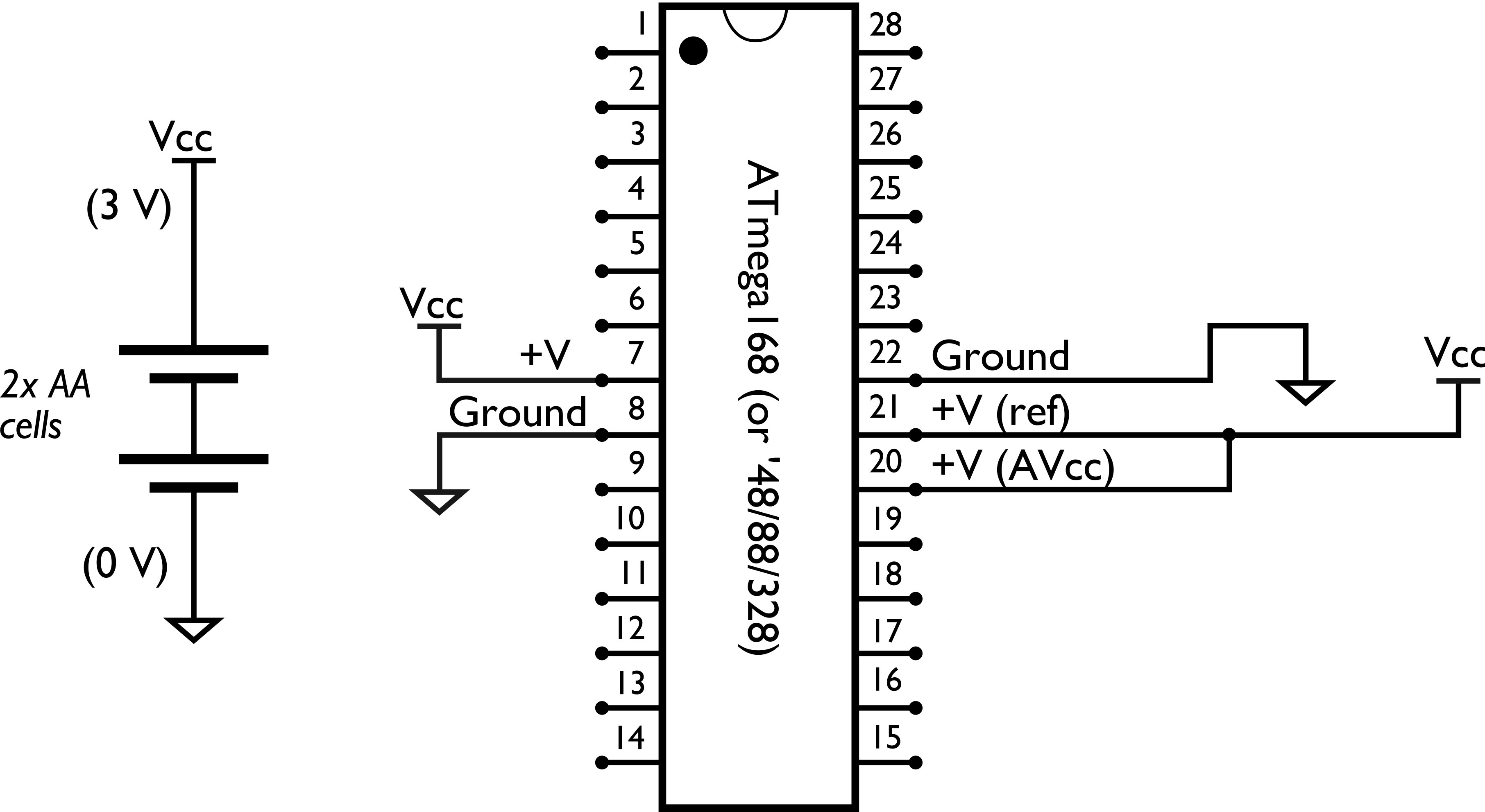
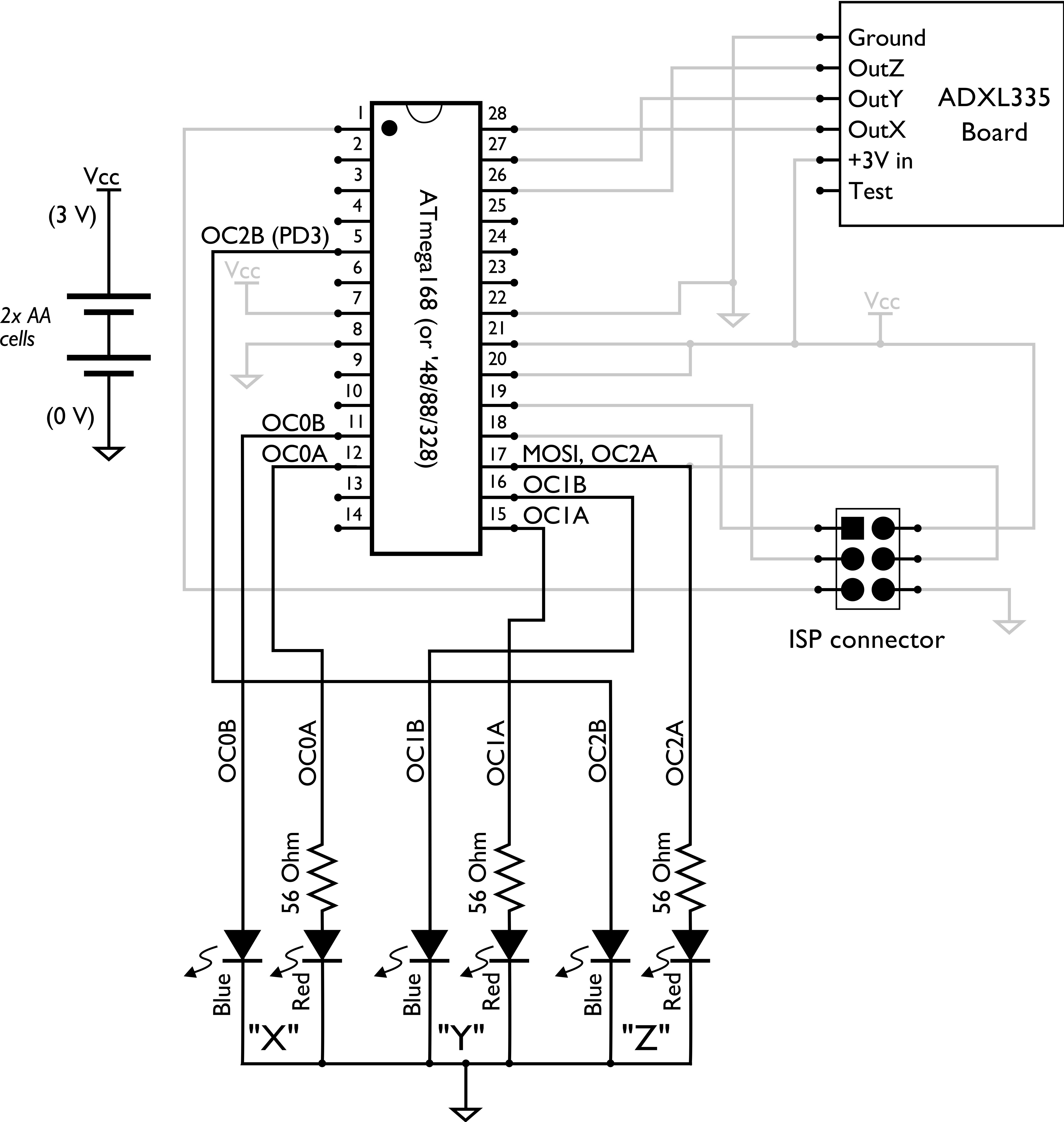
Let’s start at the beginning. We’re using an ATmega168, a popular AVR microcontroller*, which we will power at 3 V, from 2 AA cells. (3 V is a good choice to make both the chip and accelerometer happy.) The circuit diagram above shows the essential power supply connections for the AVR. We’re also using the 3 V power supply as the reference input for the analog to digital converter.
*Note 1: The other AVRs in the same family will work too, ATmega88, ‘168PA, ‘328P, etc. Note 2: If you’re new to AVR, you may want to look at our list of resources for getting started.

The next thing that we add is the 6-pin ISP header, which is necessary for programming the microcontroller through a standard ISP interface such as the USBtinyISP(also from Adafruit).
Now, the circuit diagram thus far– with just power supply and ISP connections –is common to a lot of our projects, which is why we designed those ATmegaXX8 boards in the first place.
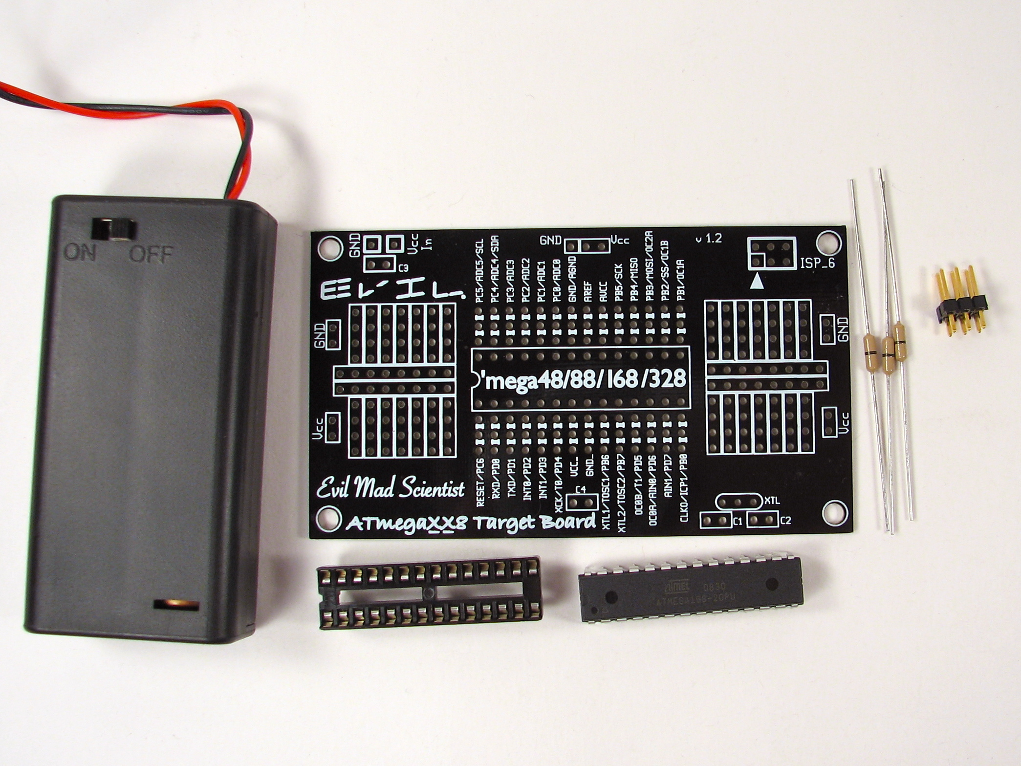
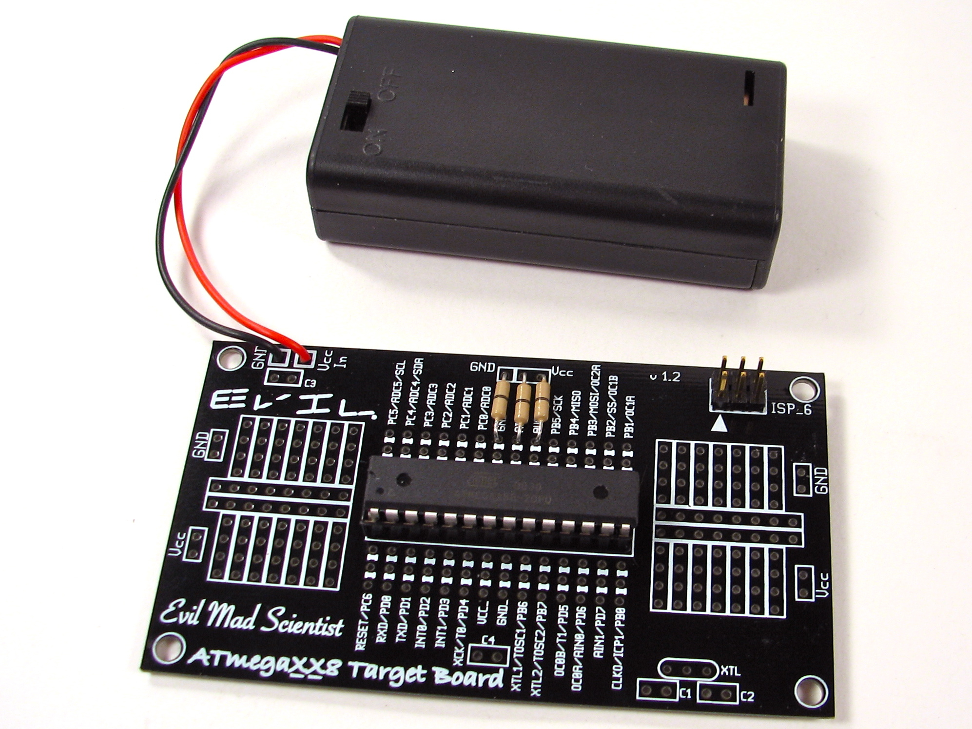
So here is the breakout board, AVR, 2 x AA battery box, and header. The three wire jumpers (like resistors with one black stripe) are used to connect pins 20-22 to power/power/ground. Having put this together, we have built the circuit shown in the last circuit diagram.
Next, we want to add the accelerometer board.
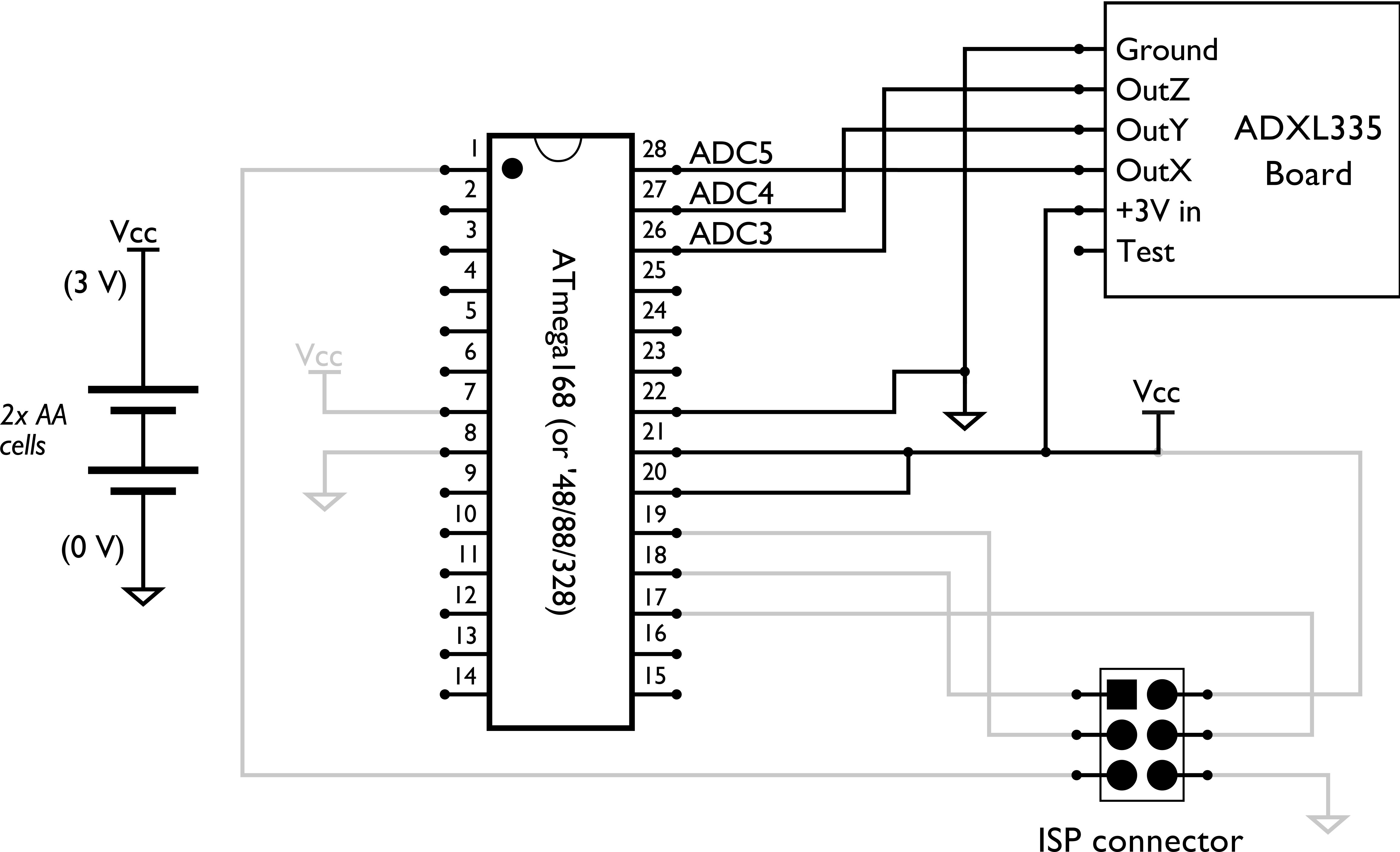
There are six pins on the ADXL335 breakout board. Two for power and ground, three analog outputs for X, Y and Z, plus a “test” pin that we can leave disconnected. We’re going to connect the power supply up first and then wire up the X, Y, and Z lines to the analog inputs of our microcontroller.
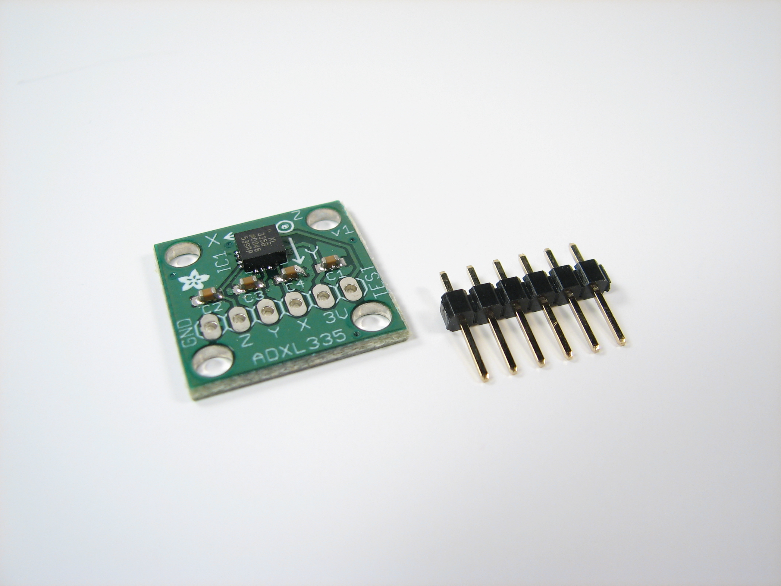
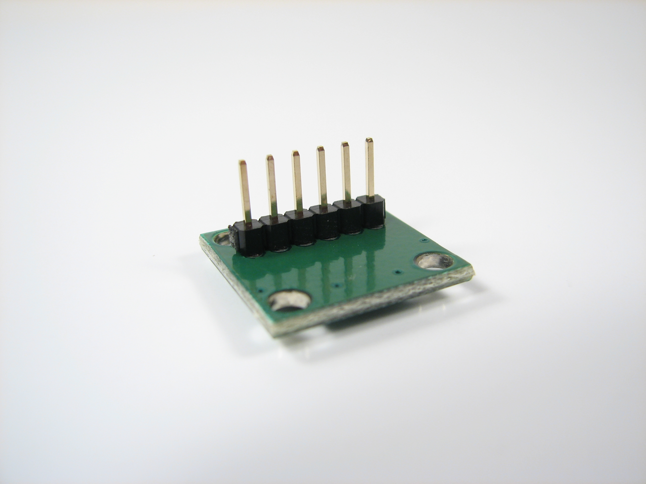
First, solder the 6-pin header to the ADXL335 breakout board.
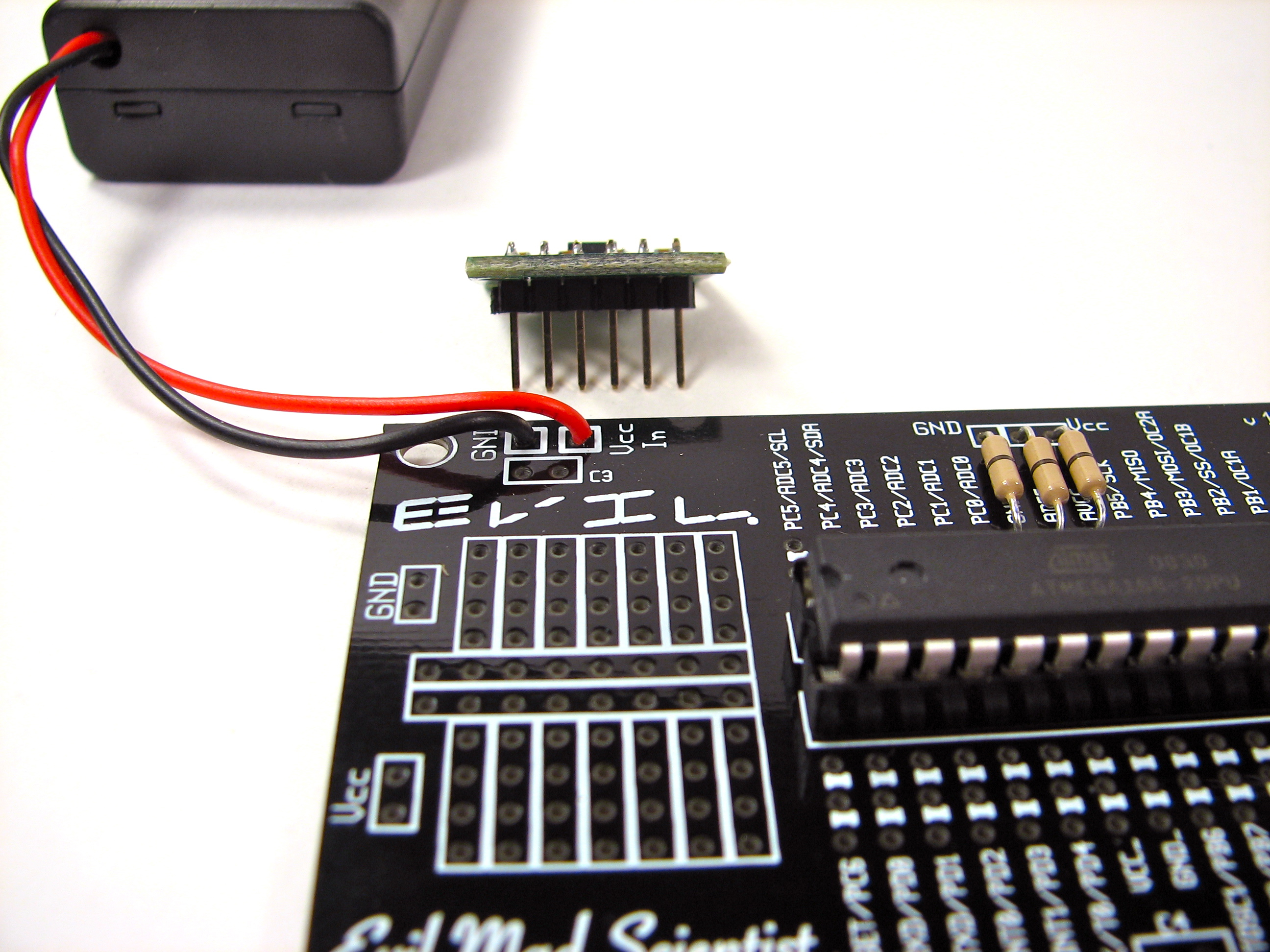
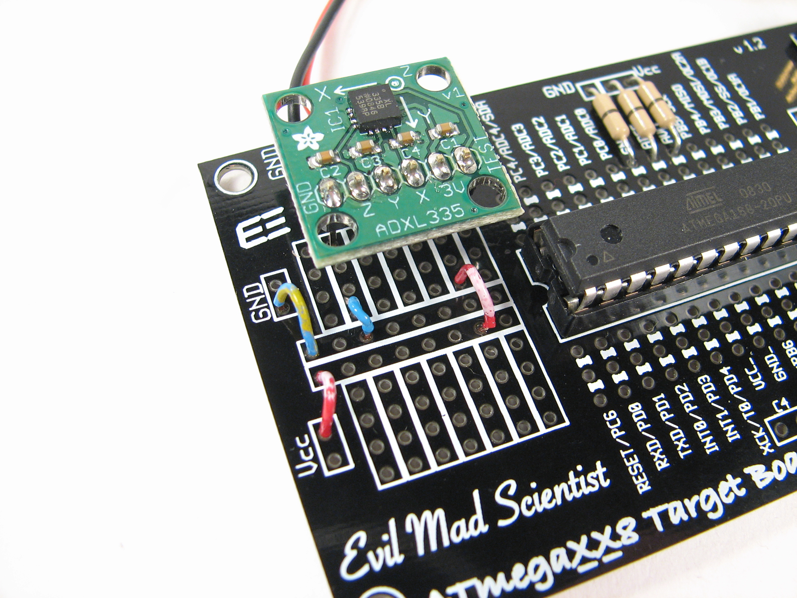
Next, we add that board to the breadboard-style proto area on the side of the microcontroller board. The locations inside each white rectangle are internally connected (and not connected to anything else).
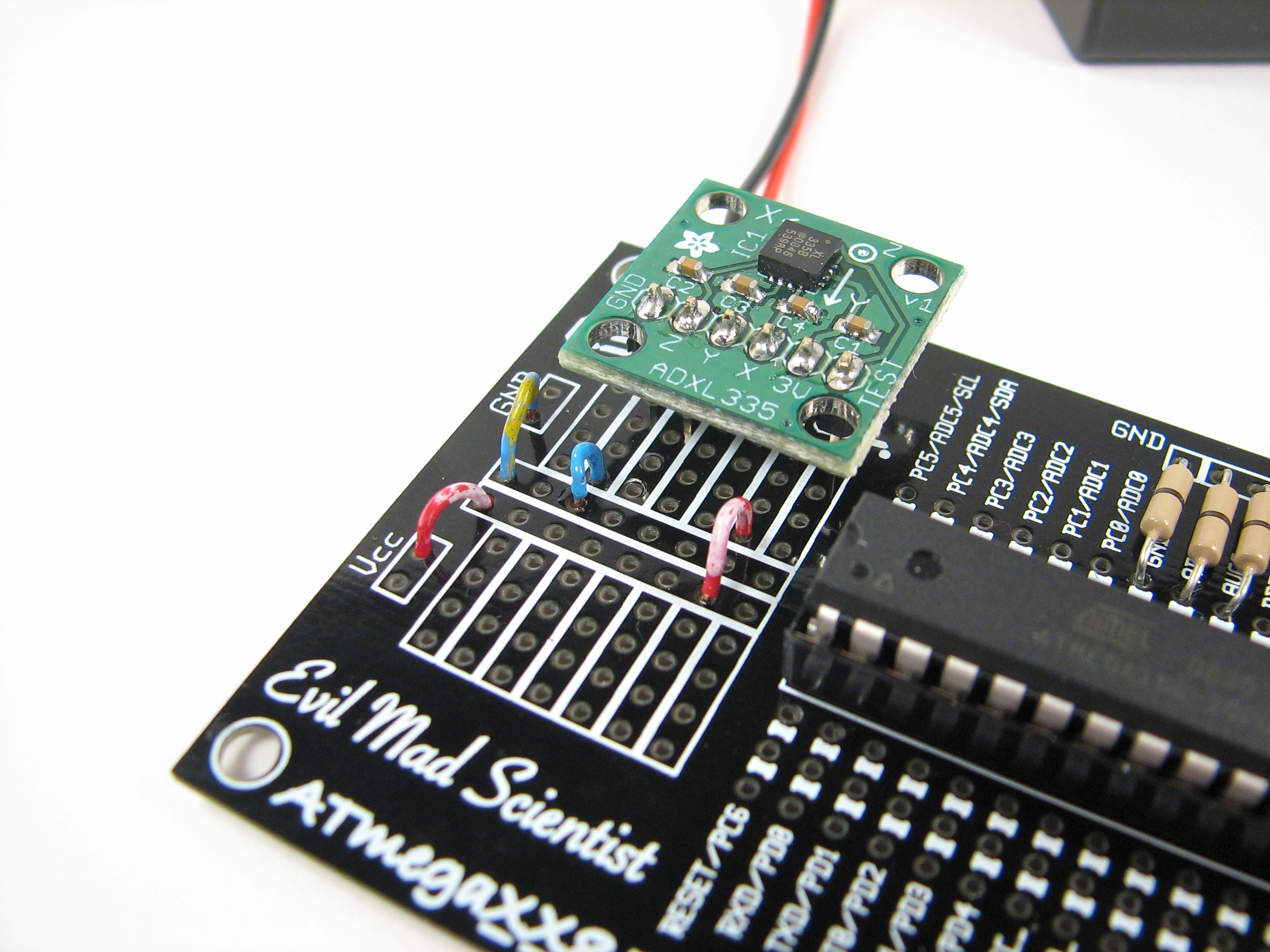
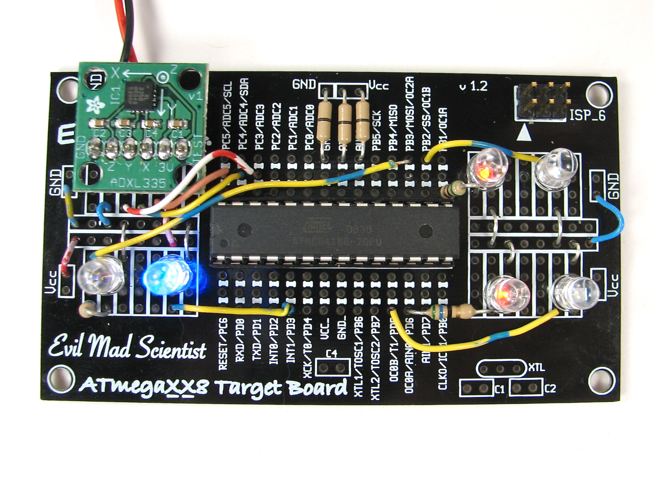
Here, we wire up the 3 V and ground lines of the accelerometer board. Ground comes from the “GND” terminal on the upper left to one of the middle stripes through a blue wire, and then through another blue wire to the far left pin of the ADXL335 board– the one labeled GND. Similarly we connect Vcc (“positive power supply”) to the 3V terminal through a couple of red wires. (The perspective of this photo makes it hard to see which pin of the ADXL335 board goes where– it’s easier to see in the photo above this and to the right.)
Now that we’ve wired up the power supply connections, we can wire up the X, Y, and Z analog lines.
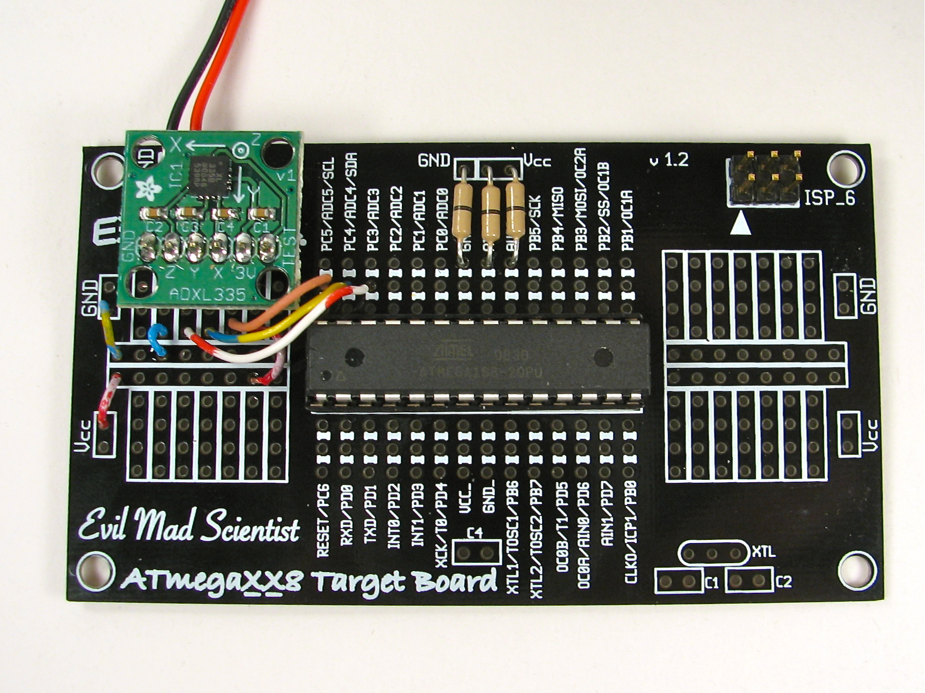
To do this, we add three wires. “X” goes to “ADC5”, “Y” goes to “ADC4”, and “Z” goes to “ADC3.” Having done so, we are now caught up to the last circuit diagram.
Next, we will add some output LEDs that the AVR can drive to indicate the acceleration values as it reads them out.
Here, we add two LEDs (one red, one blue) for each of the three axes.
The big idea is that when there is no acceleration in (say) the X-axis direction, both X-axis LEDs are off. When it detects acceleration one way, the red LED lights up (and brighter, the higher the acceleration is) and it lights up blue for acceleration in the opposite direction. (Naturally, the other two axes work the same way.)
To do this, we’re using the pulse width modulation outputs from the three timers (timer 0, timer 1, and timer 2) on the microcontroller. Each timer has two outputs, called “output compare” pins A and B, which go to the two LEDs. The six outputs are called OC0A, OC0B, OC1A, OC1B, OC2A, and OC2B, and are hooked up to the LEDs as indicated in the diagram. (No resistors are needed on the blue LEDs, because the forward voltage of those is 3.6 V– we will not approach their rated current, ~25 mA, with our 3 V power supply.)
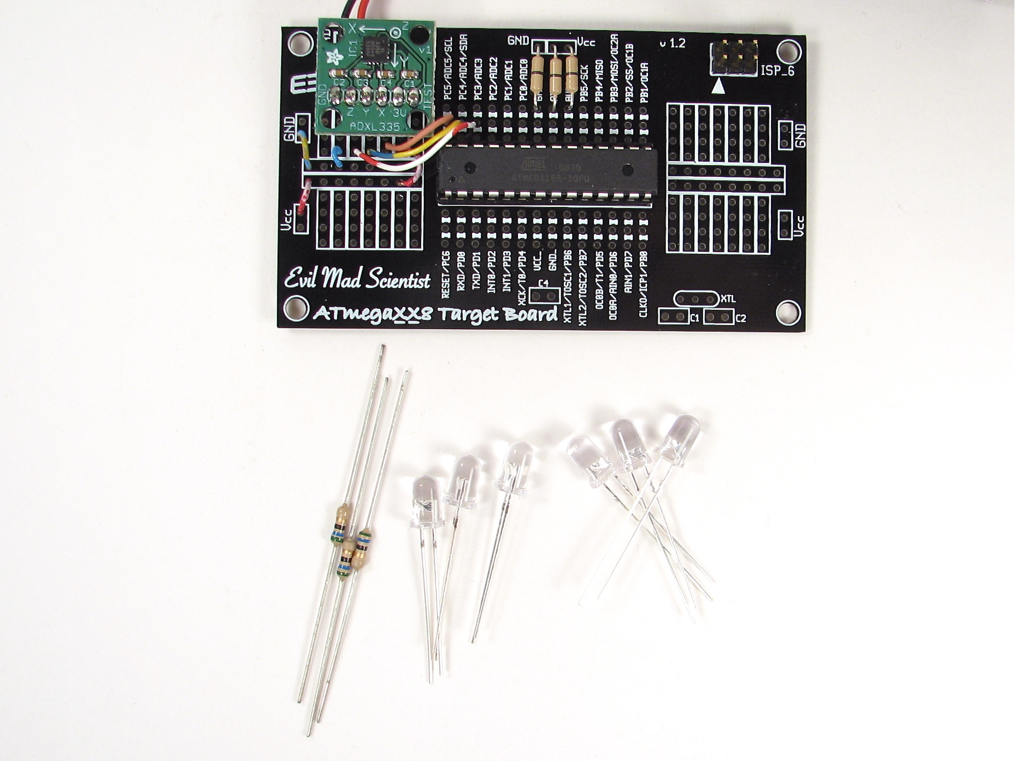
Our new parts: six LEDs (three red, three blue) and three resistors.
First, we’ll add the LEDs for the X axis.
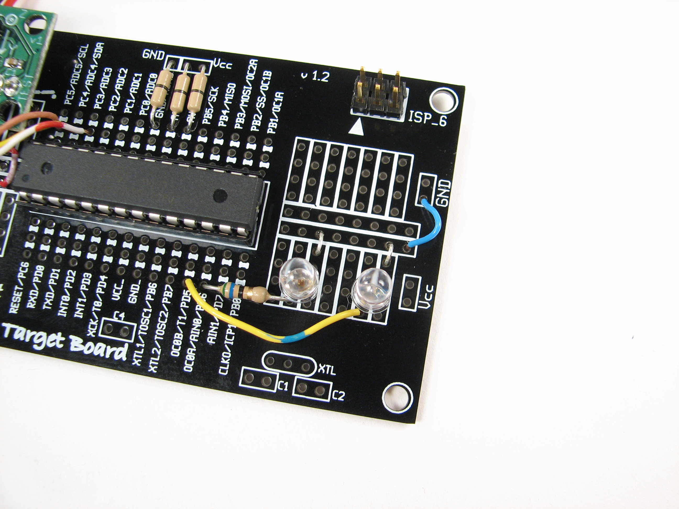
OC0A goes through the resistor to the LED, to ground. OC0B goes directly through that yellow wire to the blue LED, to ground.
You can download the firmware program (C code) for the AVR here (11 kB .ZIP file). It’s a very simple AVR-GCC program, licensed under the GPL. It reads in three analog
inputs sequentially, and lights up the six display LEDs depending on the values that it reads.
Once you’ve gotten the AVR programmed, it should be ready to go and show you outputs that depend on the acceleration.
So far, we’ve only got the output LEDs for the one axis, but you can already try it out.
As you shake it, even fast, you can see the LEDs responding to motion along the X axis.
If you aren’t wildly swinging the board around, what you’ll see is just the steady-state gravitational acceleration displayed. You might call it a tilt sensor, and it can tell you which way is up.
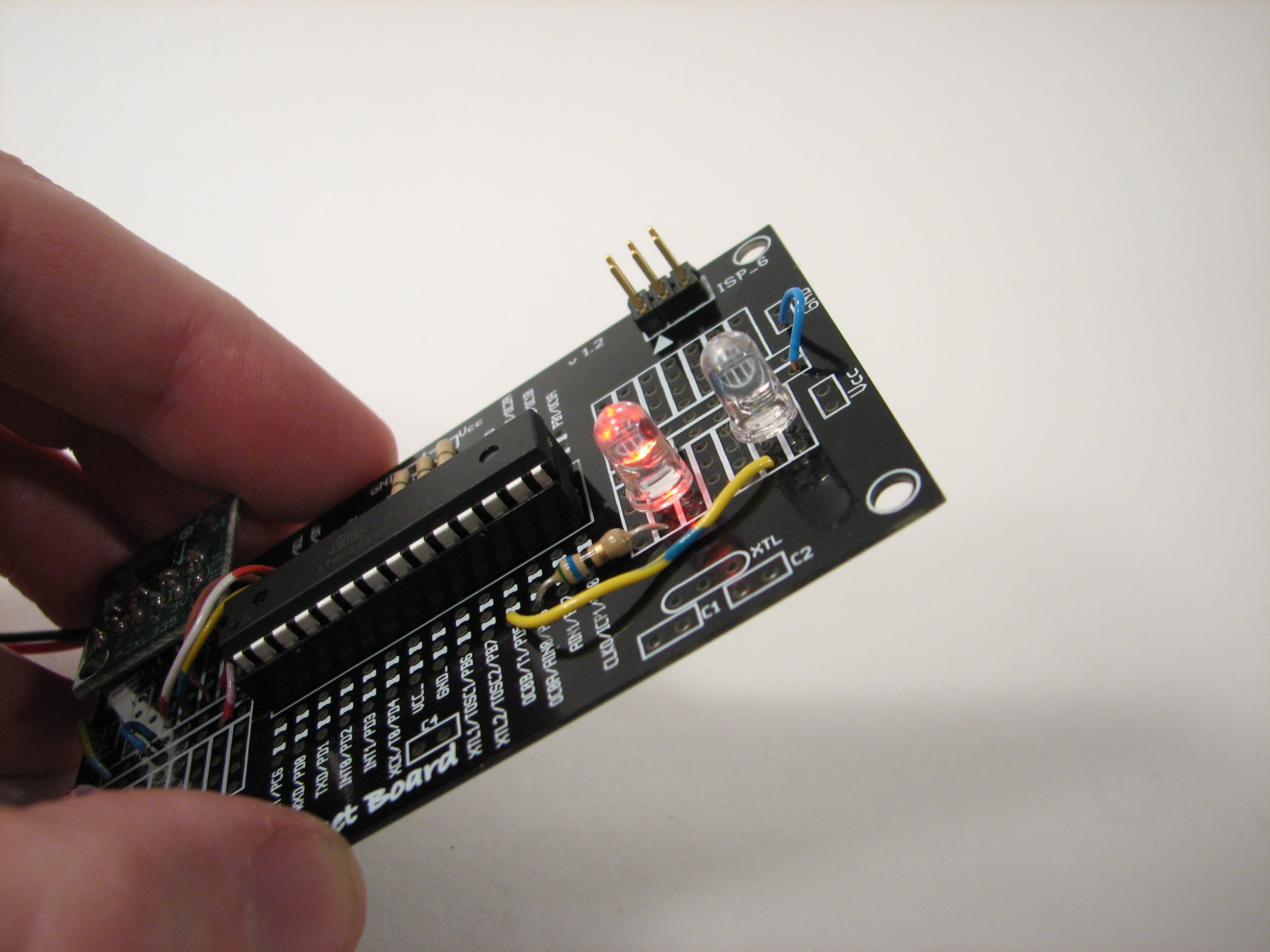
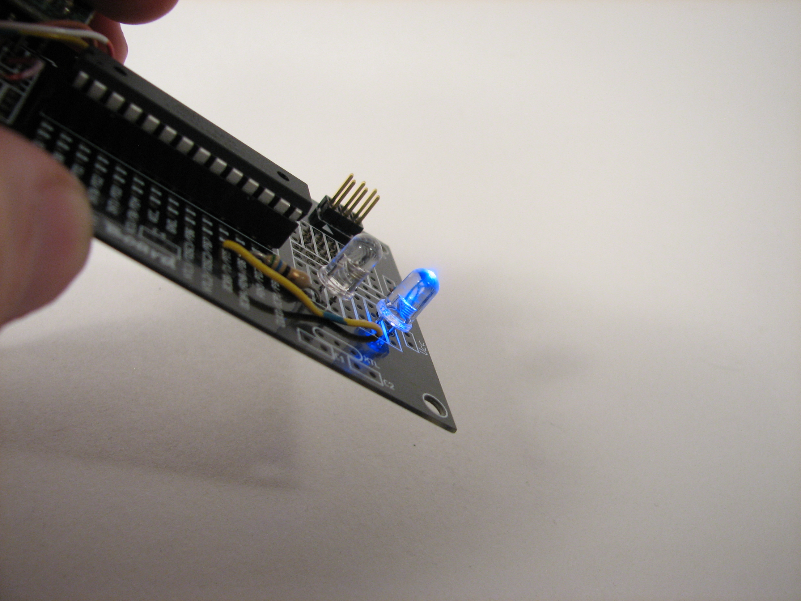
If we tilt our board left or right, such that the X-axis is now pointing slightly up or down (slightly with or slightly against gravity) you can see the X-axis LED pair, shown here, switch from red to blue. (Which way is X? It’s written on the circuit board, and also in the datasheet for the accelerometer.)
Finally, we add the Y and Z indicator LEDs.
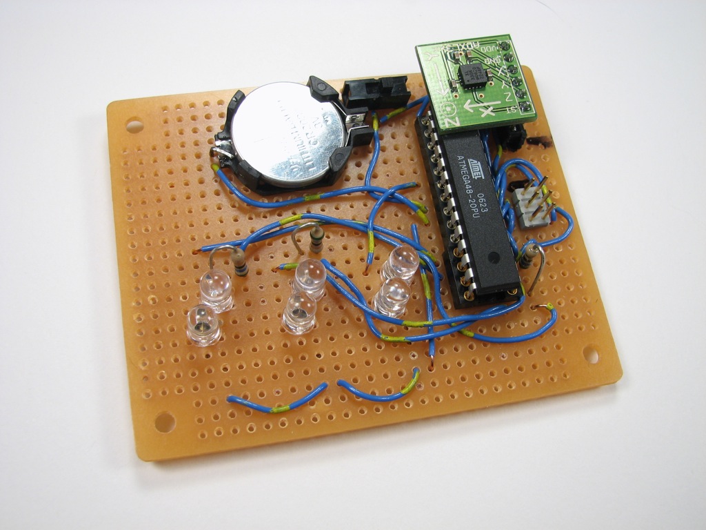
And here’s the completed project. The “Y” LED pair is in the upper right, connected to OC1A and OC1B. The “Z” LED pair is in the lower left, requiring one longer wire from MOSI/OC2A to the red LED for the Z axis.
Now, it’s sensitive in all three directions and has the capability to tell you what it sees. Lying flat on our (not particularly level) photography table, the X and Y axes are reporting near-zero acceleration. There isn’t much tilt in X or Y. The only bright LED is the blue one for Z, because there *is* a strong vertical acceleration. Naturally, the red Z LED comes on instead when you flip it upside down.

Hi,
How can i use the AVR with accelerometers into a app. I use RealBasic, is there anyway of hooking it up?
Keepersgain
sure you could use this with REALbasic. But you will need something to convert the analog voltage outputs of the device into serial data you can get into the RB app. There are lots of AD boards and things that will communicate serially, but the easiest solution might be to write the software for the same AVR controller here. Do those chips have serial output? You would have to send the data upstream to an RB app to read it.
Most microcontrollers use a TTL level serial bus too, so in order to communicate with an RB app you’ll need to level shift that. Or use one of the Arduino boards that are USB enabled that already have the FTDI stuff on board.
It might also be possible that there are accelerometer boards that already have serial data outputs instead of the analog ones. That would greatly simplify things as you would only need the level shifter and could forget the pic in the middle.
Thanks! Recently gave your target boards away to friends as gifts. Nice intro on how to use them.
Last year I needed to create a circuit for my Mechanical Engineering Capstone project. Since we aren’t electrical engineers, it seemed like an almost impossible task. Stumbled on to this site and found the tutorial, and managed to modify the code (barely).
Anyways the project was a wearable airbag that would inflate after detecting falling. The idea was to strap this into a jacket for elderly person so they wouldn’t pop a hip. The AVR did some quick math and hit a 12 VDC relay to inflate. If it weren’t for this article I wouldn’t have graduated. Thanks for the update!
I bought the ingredients for this, but decided to try rigging it up on my Arduino first.
To calibrate it, I printed the X,Y, and Z values out on the USB port, and found the midpoint. That worked fine when it was plugged in, but when I tried to run it off of battery, all 3 green lights would come on and stay that way no matter which way I tipped it.
So I figured the voltages were different. I added a line from the 3 volt supply to an analog input, and read that value and divided by 2 for my midpoint. Then it worked fine, but then I soon found out the battery was just about dead.
I put in a fresh battery, and tried it without reading the voltage, and it still worked fine without a battery. I guess what was happening was the voltage was too low for the 3v regulator to maintain the 3 volts necessary for a consistent reading.
I still like the idea of using a measured value for my midpoint instead of an observed value.
> and it still worked fine without a battery
I mean it worked fine both plugged in and on battery.
After looking at your code and seeing that you’re midpoint is 128, (after dividing by 4 to get to 8 bits), I realize that on the Arduino, the value is scaled to the 5v supply the AVR uses, but my accelerometer values are scaled to the 3.3v I’m running the accel off of. That’s why my "observed" midpoint is 350. Let’s see- 1024*3.3/5/2 = 338, pretty close to my observed 350.
One question- when I build this on a target board, can I run it with Arduino code? I think I can download the Arduino bootloader from the Arduino IDE through my Adafruit programmer, and then download my program through it. Will that work?
A few things to keep in mind if using Arduino:
0.) There’s no default connection to AREF; you need to hook this up on your own.
— If you don’t hook up AREF to the same voltage that goes to the accelerometer, you’re not going to read anything sensible.
1.) The accelerometer is not designed to handle 5 V input.
— Using 3.0 V from a battery to AREF and to the accelerometer is a good idea.
2.) The accelerometer outputs are ratiometric.
— It should not matter whether your 3V source swings around a bit– the ratio of the outputs to AREF should stay the same, to within a few percent.
3.) The Arduino varieties that run at 16 MHz are not designed to run at 3 V.
— Unless you have a lilypad, Arduino Pro, or one of the other varieties that runs at 8 MHz, you can’t run the chip itself off of 3 V DC. That’s just due to the datasheet.
So, I’d recommend running the Arduino board at its normal power, and hooking the battery voltage just to AREF and the power input of the accelerometer. Make sure that the battery ground is common to the Arduino ground, and then hook the accelerometer outputs to the Arduino inputs. Should work well.
>I think I can download the Arduino bootloader from the Arduino IDE
>through my Adafruit programmer, and then download my program through it.
Yes, that’s correct. You can also add a serial port to the target board to program it through a USB-TTL cable, once you’ve flashed the bootloader: http://www.evilmadscientist.com/article.php/avrserial
—
Windell H. Oskay
drwho(at)evilmadscientist.com
http://www.evilmadscientist.com/
Thanks Windell!
There’s a 3.3v supply in addition to 5v on the Arduino, I was using that to power the accelerometer. I didn’t know what AREF was for, now I do- "Analog REFerence". I’ll try hooking the 3.3v to that to, and dispense with my software scaling. I should get a midpoint of 512, right?
I soldered it together on a target board yesterday, and it works fine. One problem though- I flashed it once through my Adafruit USBtiny, and that worked, but now when I try to program it I get "avrdude: initialization failed, rc=-1". I tested my USBtiny on a larson scanner and it still works fine. Is there anything you can think of that allows it to only flash once? If not, I probably disturbed something when I double-sticky taped the battery box onto the back. Or maybe when I soldered the other 4 LEDs on, I flashed it when I had the first two on like you say in the directions. All 6 LEDs work fine with the first program I flashed, but I’d like to swap X and Z because I swapped those lines on the analog input.
I put a female header on the target board for the accelerometer. I didn’t feel like soldering down a $25 part, and this way I can swap it back and forth to the Arduino. It’s a little loose though, so it’s not as accurate.
Aha!
Looking over the circuit diagram, I see that pin 17 is hooked to both the ISP connector and the Red Z LED. I unsoldered the wire to the LED, and now I can program the chip again.
Any way around that, short of putting a switch in there?
It’s important that the ISP lines can be pulled high or low. If the effective resistance to ground of one of the pins is too low– for example, if you put a red LED and no resistor there, it can’t be pulled high with the small amount of current that can be sourced by the ISP programmer.
If the AVR runs at 3 V, a 56 ohm resistor in series with the resistor gives (roughly) 20 mA. If the AVR is running at 5 V, then you’ll need a larger resistor to keep the current– try 150 ohms or higher.
—
Windell H. Oskay
drwho(at)evilmadscientist.com
http://www.evilmadscientist.com/
I’m doing it exactly like that, a red LED with a 56 ohm resistor, supplied by 2 AA batteries. Actually it’s not using the batteries when programming, it’s using the power from the ISP programmer, I have no idea what voltage that is.
Note that this version is NOT using the Arduino, I’m using your target board as described on this page. I can program it just fine with the line from pin 17 to the resistor ahead of the LED disconnected.
Right.
If you’re using the power from the programmer, then it’s probably 5 V, and the situation is still as I described. It should work fine if you instead power it from the battery while programming.
—
Windell H. Oskay
drwho(at)evilmadscientist.com
http://www.evilmadscientist.com/
But I can’t power it from both the battery and the programmer at the same time right? I was under the impression Bad Things® would happen. I remember now, that’s what the jumper is for on the USBtiny isn’t it? I just pulled the jumper off the USBtiny, and sure enough the lights don’t come on.
:
:
Yep, it works fine. I resoldered the wire, left the jumper off the USBtiny, and tried programming it with it powered by the battery. It worked!
You da man, Windell.
The obvious question:
Can we expect a kit?
I don’t see a need for a kit around this project; all the parts are pretty easily available. :)
—
Windell H. Oskay
drwho(at)evilmadscientist.com
http://www.evilmadscientist.com/
Hi there. I’m interested as to how you set the threshold points for each of the three axis of the ADXL335. The way I see your application, an LED would light up if it detects the minimum change in a particular axis orientation.
In the AD datasheet, it only specifies that the sensitivity for the accelerometer is 300 mv/g. I am assuming that you also used this as the basic transfer function for your ADC. Or did I miss something from the specification sheet?
Nice site by the way. Keep the projects coming.
There’s no thresholding– it lights up from 0% of the time to 100% of the time, depending on how strong the signal is.
Windell H. Oskay
drwho(at)evilmadscientist.com
http://www.evilmadscientist.com/
I’ve been looking around the web for some plans that use an accelerometer. Has there been any consideration towards adapting it to work like a variable sensitivity geophone where:
1) Where it uses something like a variable resistor to make it more, or less sensitive to movement, or even separate variable resistors for each of the X, Y, and Z
2) Where it uses more LEDs to indicate the strength for each of the X, Y, and Z
I wanted to create a device that utilizes Bluetooth, accelerometers and possibly gyroscopes…
This device would connect to iPhones, android, etc..
What I would like to know is how would I get the components (I.e. – accelerometers, etc ) to transmit this info over to the iPhone via Bluetooth…
What would I connect the components up to? To be able to transmit the info. Via bluetooth…
Hopefully what I’m asking makes sense..
I’m just learning all this stuff.
A good example is how does the components in the Wiimote communicate ‘real-time’ info to a hacked iPhone… I use the Wiimote to play games on my iPhone
if (ADarray[0] >= 128){
DDRD &= (0xFF – _BV(PD6));
OCR0A = 0;
DDRD |= _BV(PD5) ;
OCR0B = (unsigned short) (2*(ADarray[0] – 128));
}
else {
DDRD |= _BV(PD6) ;
OCR0A = (unsigned short) (2*(127 – ADarray[0]));
DDRD &= (0xFF – _BV(PD5));
OCR0B = 0;
can someone explain to me that part of the code please; i don’t understand is ADout vlaue comapred to 128!
Just wanted to say thanks for posting this project. It was the first AVR project I tackled and the instructions made it a breeze to set it up.
I’m already looking for the next project!
Hey, so I loved this article…I’ve been meaning to setup a circuit with a MIcrocontroller and a few accelerometers..then transmit this info. Via Bluetooth to my cell phone…
I need some help as to what type of Bluetooth would I need to comm. W/ my phone and solder to my board w/ the accelerometers and MIcrocontroller.
L2cap is the comm. Protocol..