


One of the distinguishing characteristics of beginner-friendly microcontroller platforms– Arduino, PICAXE, and a few dozen others– is that they neatly wrap up and hide the nuts-and-bolts details of interfacing with the hardware.
Like everything else, it’s a blessing and a curse. The benefits are clear: A new user who has just acquired an Arduino can plug it in, blink an LED, and have a working demonstration of two-way serial communication in just a few minutes.
The drawbacks are a little harder to see. When you just use one line of initialization that calls a “library,” it’s easy to overlook exactly what’s involved: how many lines of code have invisibly been added to your program? What memory structures have been allocated? What interrupts are now going to disrupt program flow and timing? There’s also a portability issue. We often hear from people who got started with Arduino but now want to explore other AVR microcontroller systems, and don’t know how or where to start the migration process.
In what follows we discuss a minimal setup for serial communication with AVR microcontrollers, and give two example implementations, on an ATmega168 and on an ATtiny2313. While this fundamental “AVR 101” stuff, we’re approaching the problem (this time) from the migration standpoint. Suppose that you had an Arduino based project, where you relied on serial communication– using the library functions–between that hardware and your computer. From there, how would you migrate to a stand-alone AVR microcontroller with similar functionality, or even to a different microcontroller?
The answers, of course, are (1) that you have to hook things up correctly and (2) it’s nice to have some simple and lightweight set of routines as a good starting point.
To begin with, we need a good working cross-platform example of two-way communication between the host computer and the Arduino. We chose as the starting point the Processing sketch (example program) “Serial Call-Response” by Tom Igoe. This is actually a two-part program, where one half runs on your computer and the other half on the microcontroller. What we’re doing is to create a functional clone of the microcontroller program, that can still talk to the host-side program (which is still running in Processing on your computer).
Let’s look at the chips:
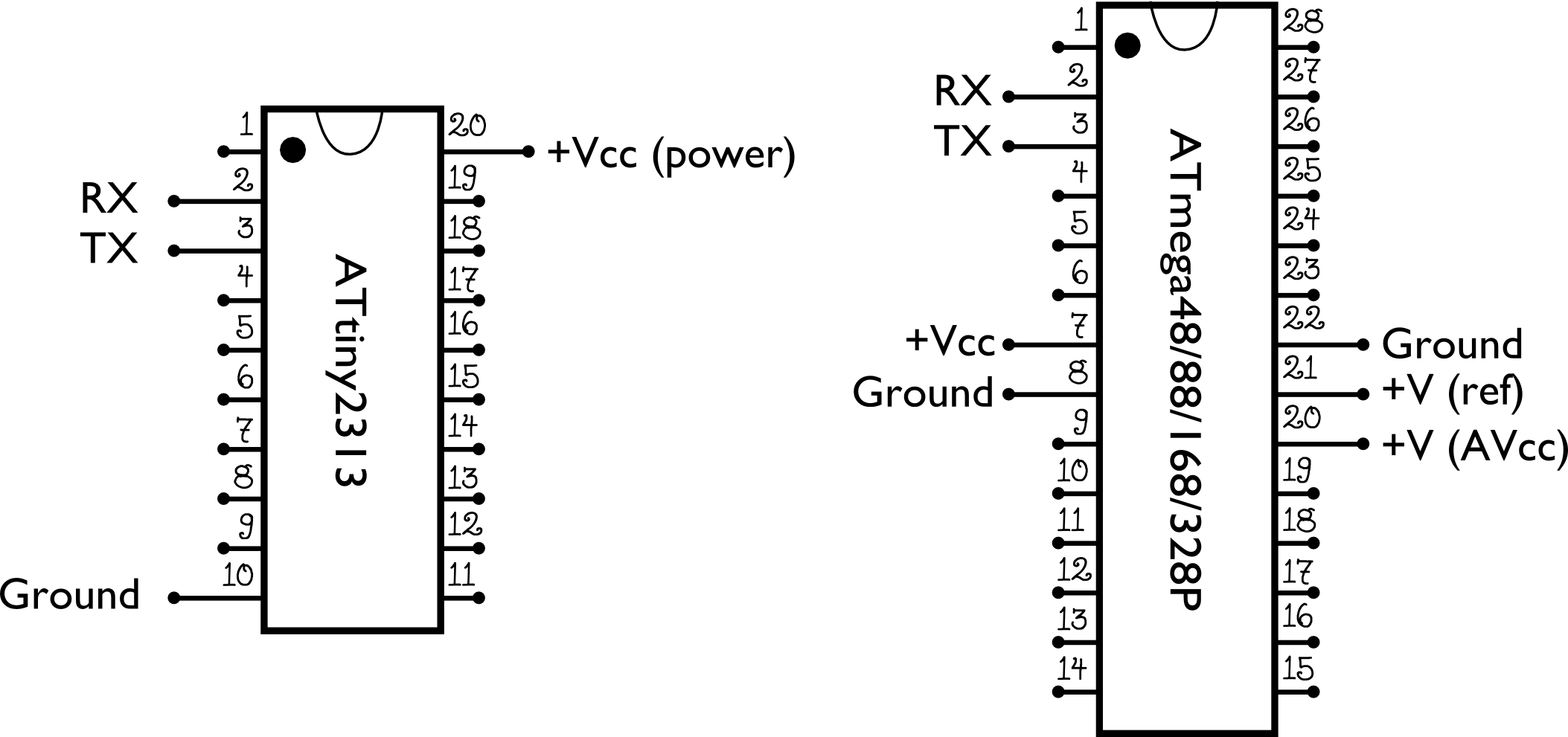
We’ve drawn the ATmega168 and ATtiny2313 here, with the pinouts for power supply and the serial port transmitter (TX) and receiver (RX) pins highlighted. These are some but (probably) not all of the pins that you’ll need. For example, if you want to program the AVR in circuit, it’s often best to do that with an ISP programmer, and our article about
minimal target boards explains how to hook one up.
Back to the serial ports. If you look in the datasheets for these chips, you’ll find each serial port labeled as a “USART,” for Universal Synchronous and Asynchronous serial Receiver and Transmitter.
Now, the microcontroller USART pins are designed to operate at logic levels– between 0 and 3-5 V. This means that they can’t directly hook up to RS-232 without a level adaptor. They also aren’t set up for directly hooking to USB, so an adapter of some sort is usually needed unless you’re talking directly to another microcontroller.
Our adapter of choice is the FTDI USB-TTL cable:
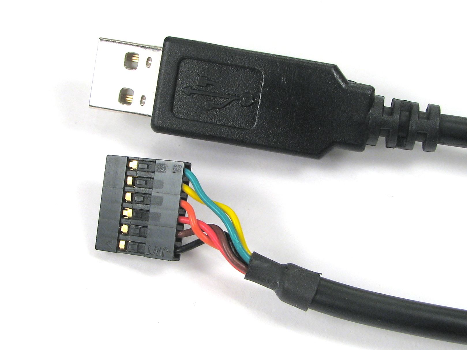
This cable has an integrated circuit built in that translates between a microcontroller’s serial port (USART) and USB. (That’s in fact the same chip that the Arduino has on board for the same reason.)
Here’s how to hook it up to one of the microcontrollers:
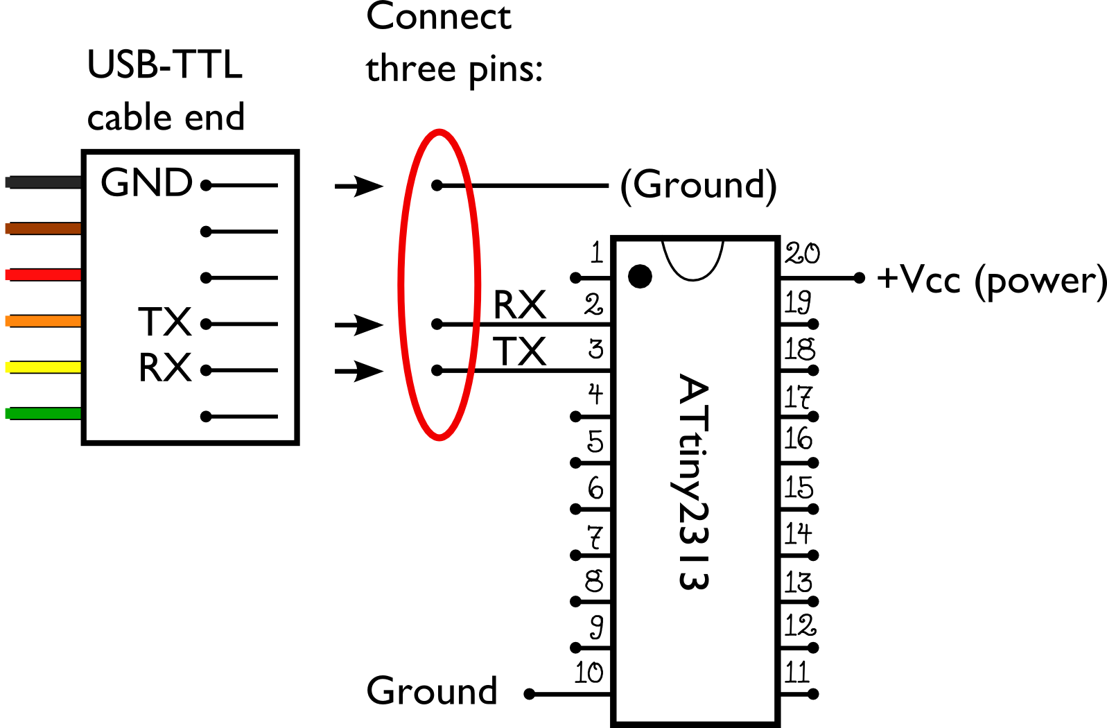
Three pins on the connector are relevant for us: TX, RX, and ground. (Ground so that your computer and microcontroller board have a common voltage reference.) The TX (transmit) pin of your microcontroller goes to the RX (receive) pin of the cable/computer, and vice versa.
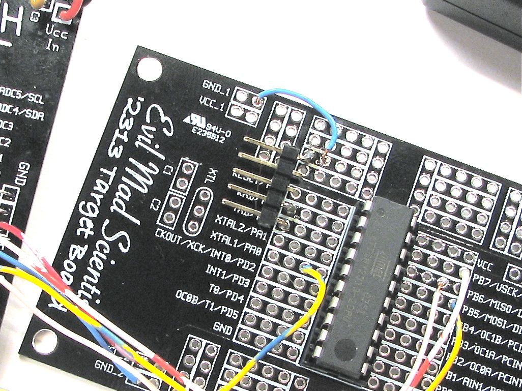
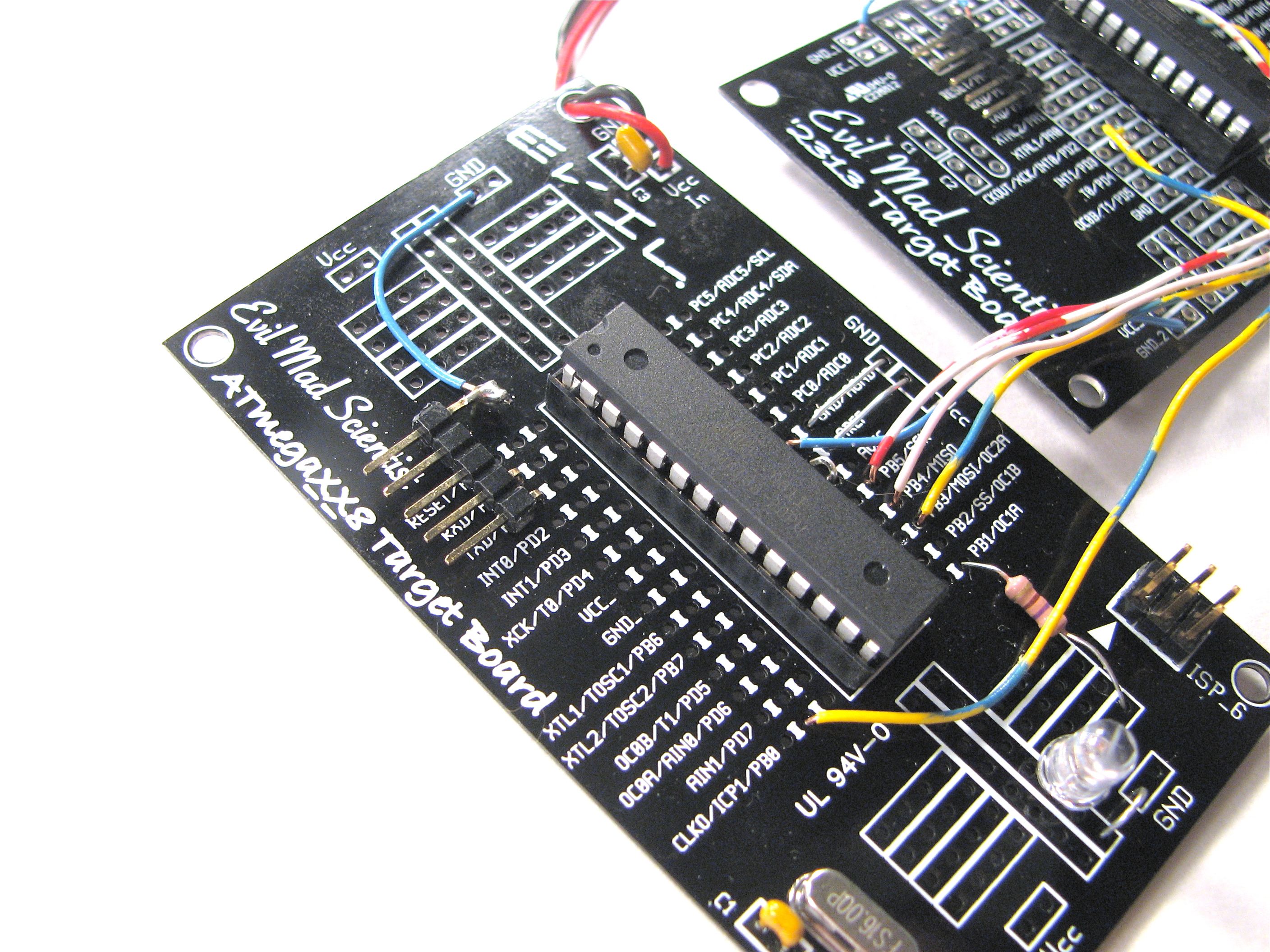
In practice you can do this with a 5 pin header with two teeth cut out, where the fifth pin is connected to ground. This can be done on a target board like we’ve done here or on a breadboard– it’s a quick way to hook things up without laying out a special board just for the serial port. The serial port pins on the ‘2313 (above) and ‘168 (below) are in the same place, so you can hook this up identically on either board.
Now that we have the physical connections ready, we need the software. You can download our example code for the ATmega168 is here (5 kB .ZIP file), and the code example for the ATtiny2313 is here (5 kB .ZIP file).
Both source code examples contain a C source file and a makefile; they can be compiled and loaded onto the microcontrollers from AVR-GCC or compatible systems; if you’ve never put code onto an AVR before, you might find our list of Resources for getting started with AVRs helpful.
The source code is meant to be a minimal implementation of bidirectional communication that can talk to the “Serial Call-Response” sketch. The two implementations, for the two different chips, are mostly identical.
We begin by setting several pins to be outputs, using the “data direction registers” defined in the datasheet. The only one of these that’s actually important is pin D1, the TX pin, on each board. We also have a place to put an indicator LED on each board, and a few other outputs for optional debugging.
The baud rate is implemented using a non-obvious but relatively compact scheme taken from the datasheet. It takes as inputs the CPU rate and the desired baud rate. The CPU clock frequency is 16 MHz from an external crystal oscillator on the ‘168 example and 8 MHz from the internal RC oscillator on the ‘2313 example. (If desired those can be changed with the fuse settings. You know about the AVR fuse calculator, right?)
Communication is implemented through four serial functions:
serialCheckRxComplete (which checks whether there is serial data ready to read), serialCheckTxReady (which checks if the serial port is ready to transmit new data), serialRead (which reads a byte of data from the serial port), and serialWrite (which transmits one byte from the serial port).
These functions work directly with the hardware; buffering and interrupts are not implemented. This makes the program lean and mean, with a tiny footprint. Working without interrupts and buffers means that you need to poll (i.e., check for new incoming data) at least as often as new data could appear– e.g., about 1 kHz or faster for 9600 baud. It also means that incoming serial data will never interrupt time-critical functions that are executing. And the memory footprint is much, much lower. This takes mere bytes of RAM to implement– making it quite practical on the ATtiny2313 which only has 128 bytes of RAM. (For comparison: the Arduino serial library usually allocates 128 bytes of RAM as a RX buffer alone.)
So, there are tradeoffs– but these lightweight functions work well enough, and should provide another helpful stepping stone to AVR, from either above or below.

You don’t often see code examples in C for Arduino based projects. I only code in pure C myself (just learning), so this article is really useful.
Interesting quote from your post: "These functions work directly with the hardware; buffering and interrupts are not implemented. This makes the program lean and mean, with a tiny footprint."
In my experience, interrupts do the opposite – they usually make the program even smaller and more efficient in terms of cpu cycles (but perhaps a little bit more difficult to debug). I’m somewhat curious as to why using interrupts would make the program larger…
An interrupt itself does not significantly affect the program size; an interrupt routine is roughly equivalent in terms of footprint to adding a function call in a main loop. However, (1) the way that serial interrupts are often used *does* tend to grow the memory footprint, and (2) a program is not "lean and mean" in my opinion when it’s bloated by unnecessary interrupts.
There are two *primary* reasons (that I can see) that you might want to use a serial interrupt. First, you have time-critical incoming data, and you want to respond to it ASAP. Obviously, a serial interrupt that parses and responds to data can be very fast and memory efficient– "lean and mean" indeed, if the main point of the program is to respond to incoming serial data quickly. The second reason is if you cannot (for any number of possible reasons) make a commitment in your program to check for incoming data at a sufficiently high rate, and you want a routine to receive and store serial data until you get around to looking at it. The latter is a good description of the Arduino serial library. If you have the resources to manage a (potentially) large serial input buffer, and don’t mind the footprint, this is also a fine method, but it’s never lean or mean.
As for unnecessary interrupts, I think that it’s important to avoid them, especially in example code. In one of our AVR applications, we need to respond very quickly when an input level goes high or low. To do this we use an interrupt, of course. But here’s the problem: Our pin-change interrupt routine cannot begin if there’s already an interrupt running. That means that if a serial interrupt routine were executing, we’d have to wait until it finished to respond to our important signal. In contrast, our serial polling routine has no trouble running the port at full speed, while still allowing our CPU to respond quickly when our signal changes value. In this context, the footprint of a serial interrupt routine would be *huge*– completely defeating our ability to respond to signals in real time.
—
Windell H. Oskay
drwho(at)evilmadscientist.com
http://www.evilmadscientist.com/
Even more interestingly (to me), interrupts can be used to make processing happen on events. The main loop can put the chip into a power saving mode until it has to do something (ADC done, comparator trigger, watchdog, timer tick…).
And then there’s context switching.. :)
Sorry to revive a dead thread but I just thought I’d mention that you can re-enable interrupts within an interrupt routine. So as long as the level change handle didn’t change any variables used by the serial interrupt handler then you can quite safely nest these interrupt handlers.