


Today we’re releasing an update to our “Peggy” open-source LED Pegboard project. Peggy version 2 has been redesigned from the ground up. And it looks… almost exactly the same. The changes under the hood are substantial, though, and we think that it’s a big improvement in many ways.
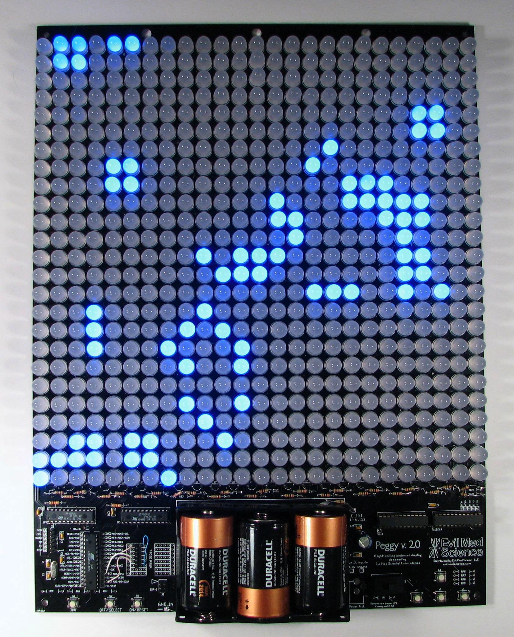
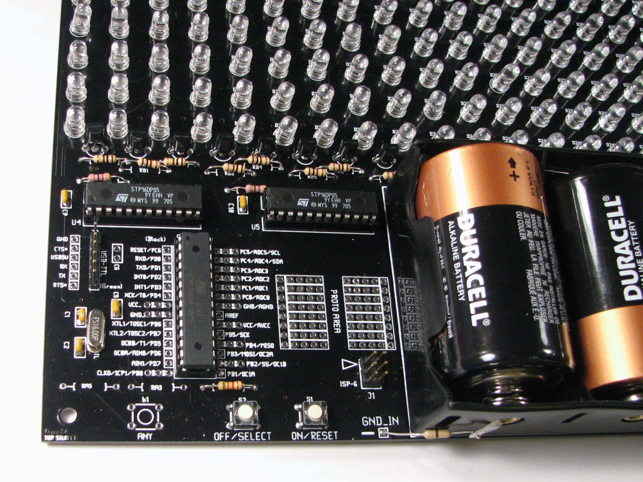
First and foremost, Peggy 2.0 still does the same darn thing: it provides efficient power to a 25 x 25 array of LED locations. Peggy is designed to take some of the sting, complexity, and mess out of playing with LEDs. It’s a versatile and powerful light-emitting pegboard that lets you efficiently drive hundreds of LEDs in whatever configuration you like, without so much as calculating a single load resistor. You can install anywhere from one to 625 LEDs, and Peggy will light them up for you.


Peggy can optionally be reprogrammed to do much more, of course. The biggest change is that the Peggy 2.0 hardware now supports simple animation capability with individually addressable LED locations. Besides the microcontroller, there are now four support chips that help to drive the rows and columns of the display. Now, we’re not talking live video feeds or long movies here (speed and memory considerations will spoil that party), but you might be surprised how much you can do with a little AVR microcontroller.
The second improvement has to do with the programming interfaces. As before, Peggy supports programming through a regular AVR ISP (in-system programming) connection, such as the USBtinyISP. However Peggy 2.0 is now also Arduino compatible: it supports programming through a USB-TTL cable, using the popular Arduino software environment. (This is the same programming arrangement that you’ll find on some of the popular Arduino-compatible boards such as the Boarduino and Bare Bones Boards.)
Other improvements and new features:
- The size of the circuit board has been slightly tweaked to 11.320 X 14.87″. The new narrower width allows multiple Peggy 2.0 boards that are lined up side by side to form an uninterrupted LED field.
- A small breadboard-style prototyping area
- 16 MHz crystal oscillator for improved timing and communications
- Extra space to add up to five optional tactile buttons including four “arrow” keys. Could come in handy if you are using Peggy as a game platform.
- Peggy 2.0 now uses the popular ATmega168-20PU microcontroller. An awful lot of existing Arduino code can run on it without modification.
- Full-size power slider switch now standard equipment.
- Still fully open source and designed to be hacked. Schematics, code, and extra access points are provided.
Here are some project ideas that might be fun to try with Peggy 2.0:
- Boring old static LED sign.
- LED clock with digits. BIG digits.
- Scrolling readerboard.
- Low-speed oscilloscope.
- FFT sound grapher.
- Mega MiniPOV!
- Add a temperature sensor in the prototyping area and make a giant display thermometer.
- Add a EEPROM in the prototyping area to store data for a long animation.
- Variable color LED panel, fading between different color LEDs in different areas.
- 14×14 RGB display, clumping three LED locations to form an RGB pixel.
- RSS reader?
- Mega-emoticon display for use in car
- Simulated animated neon sign.
- Open/closed sign that states your hours, too.
- True sprite animation
- Simple video games!
- LED status board.
- Blinkylight array for your sci-fi movie computer set.
Since the full display is addressable, there’s really a wide-open set of potential applications. As a first demonstration I wrote a version of Conway’s game of Life. It’s not written from scratch; it’s adapted from this project by David Gustafik, and the code is available under the GPL. We’re embedding a little YouTube video here; if you can’t see it, you can click through to YouTube.
How do you make it?
This project is fully documented, open source, hacker friendly, and you can approach it from any direction you want. Start with the schematics and code, or start with a circuit board and a soldering iron. It’s all yours:
- Get a kit here.
- Build instructions, schematics, and bill of materials are all wrapped up in one big PDF here (10 MB PDF File)
- Learn about programming Peggy 2.0 in a separate article here.
- The circuit board was designed in gEDA PCB, and you can download the original PCB file here; Fundamentally, it’s also source code; we are releasing it under the GPL.
- Want to talk about it? That’s what the forums are for.
FAQ:
1. What’s this all about?
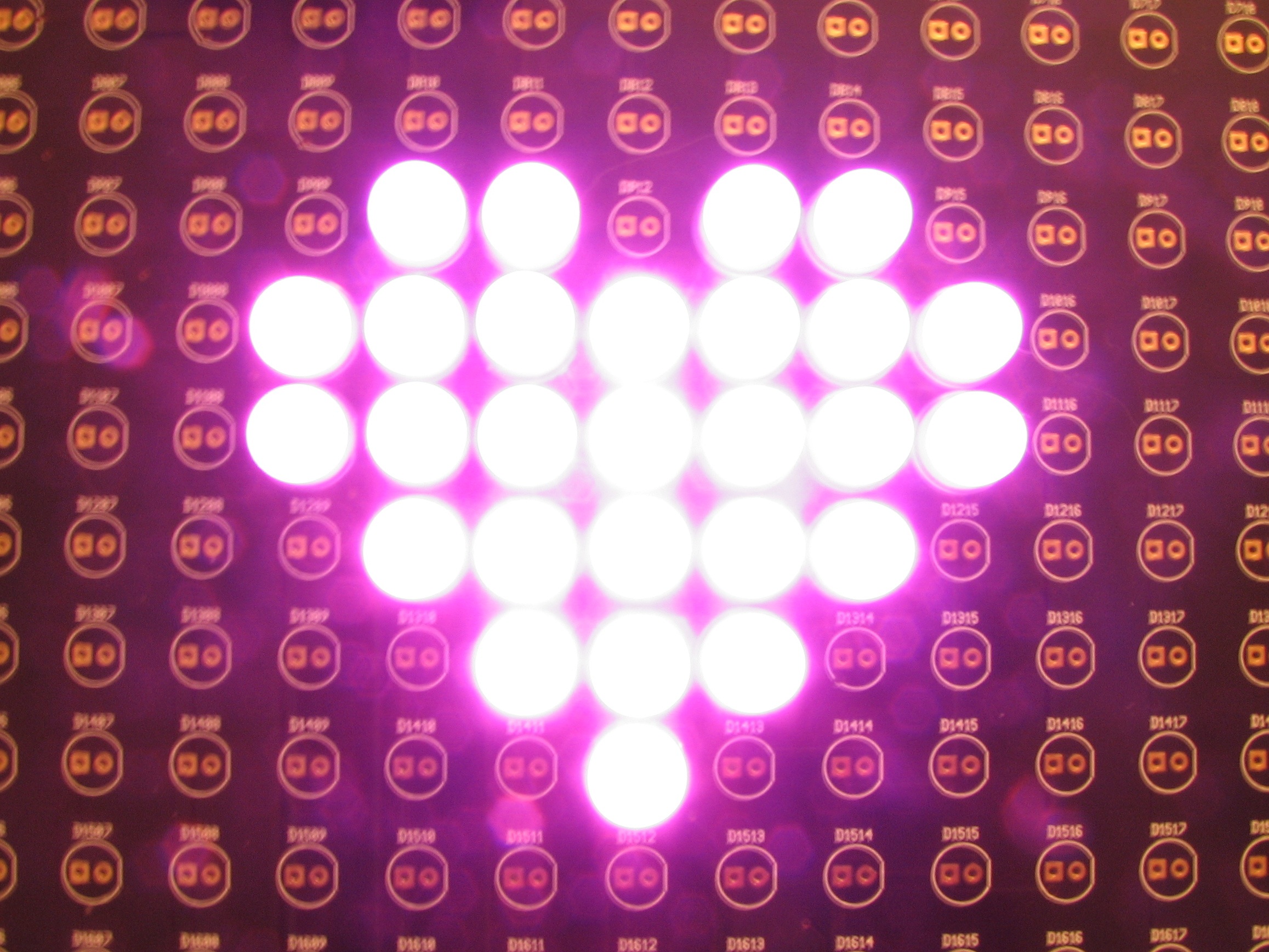
This is an easy way to drive a lot of LEDs– up to 625– in a big matrix. You can make an LED sign for your window, a geeky valentine for your sweetie, one bad-ass birthday card, or freak the holy bejesus out of Boston. Your call. It’s a versatile, high-brightness display.
The display can run off an AC adapter or batteries (3 ‘D’ cells), and is designed to run as LEDs as you care to solder into the holes, all with excellent brightness. The board can accommodate LEDs in several common sizes: 3mm, 5 mm (standard T-1 3/4 size), and 10 mm.
2. Do I have to put the LEDs on the grid, or can I position them exactly where I want to?
You do not have to place every LED on a regular grid. See the instructions for some tips on how to position the LEDs more arbitrarily.
3. Do the LEDs get soldered in the holes?
Yup.
If you do want to add sockets, go right ahead. (Peggy is designed to be hacked.) However, keep in mind that you’ll probably end up doing more soldering in total, and those sockets cost more than you might think.
4. Does the Arduino Bootloader come preinstalled on chips in the kits? Does it work? Is this the world’s biggest Arduino?
Yes, yes, and no.
Use a USB-TTL cable and tell the Arduino software that you have a Diecimila. It works well. While the board is big, it is technically not “an Arduino”, as per
guidelines issued by the Arduino team. (Arduino is the proper name of a hardware + software platform, so the term “an Arduino” is a bit misleading in any case.) Peggy 2.0 is merely open-source hardware that happens to be compatible with the Arduino software development environment. (And no, we won’t rename it Pegguino.)
5. What is the default program installed on the chips in the kits?
First, we load the Arduino bootloader onto the chips, and then we load up the default program, which lights up every LED location on the board. That way the board will work correctly if you just start using it, but it will also accept reprogramming through the Arduino environment, or (as always) accept programming with an AVR-ISP programmer.
6. Is “Peggy” named after someone?
Nope. It just comes from the term “pegboard.”
7. What does Peggy 1.0 have that Peggy 2.0 doesn’t?
- Light sensor (you can still add one if you want to, of course)
- Gold-plated circuit board finish (new finish is lead-free solder)
- Board size that’s an integer number of square inches

Saw the Peggy v2.0 at Maker Faire, awesome project!
Neat tidbit: according to Limor, maker of the USBtinyISP, that programmer is now supported by the Arduino platform, so you don’t necessarily need the USB-to-TTL cable… (I haven’t tried it yet, though)
Hmm. I use both. I know that the Arduino environment uses the USBtinyISP to burn the bootloader, but I’m not sure how (if it all) it can be used to upload a sketch as well. I’ll look into it.
—
Windell H. Oskay
drwho(at)evilmadscientist.com
http://www.evilmadscientist.com/
I got the impression that it could be used for both, though perhaps I misunderstood. I don’t have anything Arduino-like to test, so I’m curious to find out one way or the other.
The info seems to be written for people in the know. It would be helpful to get more pedantic details on programming options for those of us unfamiliar w/ the AVR ISP, and esp. any expanded capabilities via Arduino approach.
This article *does not* detail how to program Peggy, or how Peggy works internally which you might want to know for programming Peggy– it is not meant to.
We have a separate article that does give the in-depth description of how that programming works, with a couple of first examples. And, as we’ve said, we will be expanding that with additional examples and code in the near future.
As far as programming options, the two options are exactly as we said above: Use a USBtinyISP (where full instructions for use are found on the page about that programmer, linked above) or use a USB-TTL cable and the Arduino software (also linked above). Two choices, both with their own advantages and disadvantages; you can read much, much more about those options for programming and how they work on the sites that we’ve linked above.
As far as “expanded capabilities via Arduino approach,” I’m not sure what you getting at– there is no extra capability given to an AVR microcontroller by programming it through the Arduino software. (You could even argue that it has less capability because of the Arduino memory overhead and certain features that aren’t supported in the Arduino environment….)
—
Windell H. Oskay
drwho(at)evilmadscientist.com
http://www.evilmadscientist.com/
I was wondering if there might be a future version where the LED field is separate from the rest of the circuits, allowing the LEDs to be tiled in a square, as opposed to the side-by-side option currnetly available.
You want to solder 5000+ LEDs? Wow. Okay, I can sortof accept that. But, do you *really* think that everyone else does as well? The thing is, adding a separate board for the LEDs would increase the price of every kit price by at least $10, and would benefit only those people who were getting four or more kits. (And, as far as we know, exactly zero people have so far.)
From the forums:
“… nobody needs Peggy to tile better. 625 LEDs is already a lot to solder. (I *do* speak from experience!) Do you really want to solder two sets of 625 LEDs and put them side by side? If so, great! Peggy 2.0 tiles left-right just fine. But you want to do FOUR sets of 625 LEDs and put them edge by edge? Okay, you can trim off the top edges and do that too. You want to do SIX panels, you crazy person? Go right ahead: 2×3 is fine, trim 6 top edges and use the side by sides. So, we don’t even run into a problem until you want to scale up to a 3×3 matrix– 5625 LEDs to solder and several thousand dollars invested. At this point, controlling that mega matrix gets to be a little bit challenging, and you can probably find some lower alternatives where the assembly time does not become quite so infinite.
On the other hand, we do have a few ideas for possible future projects that *might* make more sense to tile… but that’s still a ways off.”
—
Windell H. Oskay
drwho(at)evilmadscientist.com
http://www.evilmadscientist.com/
I was thinking it would be good to separate the LEDs from the rest of the board but not for tiling, but for having just the LEDs on show, maybe in a picture frame. I understand it would increase the price, and there probably isn’t much call for it, but there are other reasons than solder-masochists wanting a wall of individually addressable lights. ^_^
Great work on this, this would be great in a theatric lighting situation. Anythought to adding DMX so that you can drive individual colors or shapes?
The Bill of Materials at the end of the PDF has the wrong Digi-Key# for the 2N5401 transistor. The Digi-Key #2N4401D26ZTR-ND gets you a 2N4401 transistor instead.
Probably should have said "2N5401 or equivalent" there — Either can be used.
—
Windell H. Oskay
drwho(at)evilmadscientist.com
http://www.evilmadscientist.com/
Are the 2N5401 and 2N4401 equivalent? In the design, a low signal from the demultiplexor turns the transistor on. The transistor then drives the row and the LED driver sinks the column giving you the individual LED control. I purchased the 2N4401 using the Digi-Key part #. it requires a high signal to turn the transistor on.
Oops– Yes, the 2N4401 is an NPN, and the 2N5401 is the PNP, which is what we want. (It appears that the digi-key part number was copied mistakenly from the Peggy 1.0 kit list, while only the part name itself was corrected.) The schematic pages are correct and consistent, however, and show the 2N5401 along with the symbol for a PNP transistor.
If you’re making your own matrix, you may be able to use either one, depending on how you set things up. (Using both is how we ended up getting that mistake in the first place, obviously….) The new version, Peggy 2.1, which we’ll be posting files for soon, uses higher-performance 2STX2220 PNP transistors, which use a different pinout.
—
Windell H. Oskay
drwho(at)evilmadscientist.com
http://www.evilmadscientist.com/
What else does the Peggy 2.1 include? What does the 2STX2220 allow or improve? Is the pinout just spaced differently?
I am trying to build a 50×50 LED array based on these plans, using an Arduino Mega and double the LED drivers and demultiplexors, so any improvements/speed increases would be welcome.
To do 50 x 50, you are going to have to look at the analog part of this circuit in some detail– you can’t just add more LEDs and expect things to work without evaluating the electrical consequences to the design. You should stop, back up, study, and learn to understand which currents flow when and where and why. Otherwise, things will not work how you expect. You should also evaluate the timing and duty cycle options, and figure out if this design really scales for what you’re trying to achieve.
—
Windell H. Oskay
drwho(at)evilmadscientist.com
http://www.evilmadscientist.com/
What would be involved in interconnecting 4 panels for a 50×50 matrix?
With the Peggy board I have been running sketches through Arduino to the board via USB-TTL into a USB-BUB board (USB-TTL Serial Adapter) that plugs into the 6 pin connector.
I want to attempt to send Processing sketches to the Peggy however I have been advised that in order to accomplish this I need to use PC (or MAC)-Arduino-TWI-Peggy.
Here you’ll find a comprehensive explanation:
http://planetclegg.com/projects/Twi2Peggy.html
My understanding is that the Arduino converts the serial data that comes from Processing into TWI data for the Peggy.
My question is why can’t I use the TTL cable with the USB-BUB board to run Processing sketches?
The hardware serial port pins of the Peggy 2 are available for programming the microcontroller through the Arduino IDE, but are then used by Peggy 2 to control the LED matrix while it’s operating.
There are several ways to get serial data to the Peggy 2.
One is to create a "software serial" port on an unused pair of pins. All six of the PORTC pins are available when no buttons are installed (or if the buttons are just *not pressed*).
A second way is to do as Jay Clegg has demonstrated and send serial data to the Peggy over TWI, which does require an external adapter (for example an Arduino).
A third way is to physically reroute two signals on the Peggy so that the hardware serial port is available for use while running the LED display. This is much more invasive, and requires changes to the Peggy control library to account for the difference. (Jay also has a page describing how to do this mod if you want to.)
—
Windell H. Oskay
drwho(at)evilmadscientist.com
http://www.evilmadscientist.com/
So peggy 3 will be full of those nice new RGB LEDS you have listed now?
Or a 3×3 grid of the 8×8 blocks? I’m almost ready to spring for the peggy 2 with the four square RGB pixels, but the higher resolution would make multicolor informational type displays a lot nicer. 625 RGB LEDs has got to hit someone’s volume discount
"Peggy 3" is not planned yet. We do have some complementary products in the works, but nothing designed to directly replace Peggy 2. And by the way: A display based on Matrices will be a Meggy, not a Peggy. ;)
—
Windell H. Oskay
drwho(at)evilmadscientist.com
http://www.evilmadscientist.com/
I’m playing around with a Peggy 2.0 clone on my breadboard and I was wondering why you didn’t daisy chain the demultiplexers. All it would take is one transistor and a resistor and you free up 3 more pins (tx and rx could be freed up, allowing for serial).
Is there a something I’m overlooking or is it just more convenient to give them each 4 pins?
If I were doing it again now, I would probably pick four lines to both, plus one select line to each, rather than four to each– so six pins instead of eight. (Parallel, not daisy chained.) That said, one good reason *not* to change it is that all "Peggy 2" code is compatible with all other "Peggy 2" code. We won’t change it until we make a bunch of other changes, and put a new label on it.
Also, the I2C interface that is presently supported is a multi-point interface: you can send data to more than one Peggy 2. Regular serial only lets you talk to one board at a time.
—
Windell H. Oskay
drwho(at)evilmadscientist.com
http://www.evilmadscientist.com/
Oops, my mistake about daisy chain/parrallel. You wouldn’t need 2 pins though, just 1 more, connected to the G1 of U2 and connected to a pnp through a resistor which is between Vcc and U2, G1. Also a pull-down resistor on U2,G1 would be needed. This acts like a 5th input bit.
But yeah, as you said not worth doing until it’s majorly revamped.
Excellent point about i2c’s superiority over serial when it comes to controlling multiple peggy’s however serial would allow an easier interface with a computer for people with only one peggy (probably most people :P)
Hi there,
I just found Peggy and it looks really interesting. I have a question, though: aren’t the LEDs running dim since each is only running at 1/25th duty cycle?
The allowable peak current of most LEDs is several times higher than the average allowed current, so I thought maybe you were overdriving the LEDs while they were on, then letting them rest while lighting the others. However, your schematic shows you’re using 1k current-configuration resistors on the LED drivers, which (according to the STP15DP05 datasheet) should give you about 20ma of current, which is the typical continuous-current rating for an LED.
I am pretty new at electronics so I must be missing something … what magic is letting these LEDs go to their full brightness?
Yes, the Peggy 2 is a low power, multiplexed display. Running 25 LEDs at a time, at 20 mA, uses 500 mA of current, or 2.5 W from a 5 V power supply (2.25 W from 3 D cells).
Running all 625 LEDs at standard LED current (say, 25 mA) would take more than 15 A of current and consume 75 W of power. There is, simply put, no way to get as much brightness without using a comparable amount of input power. If we did want to provide that much power, it would be a much, much more difficult design. Managing 15 A on a circuit is not trivial. The power supply would be large. We’d need fans and a circuit board with thicker copper. We’d need 50 LED driver chips instead of two. All of these mean that it would be a much, much more expensive project. Peggy is a low-cost, low-power solution good for playing with LEDs, making bright indoor signage, neat animations, and so forth. It’s *not* for lighting a room, nor grow lights, nor making an outdoor sign on the highway.
It should be reasonably obvious that there is no way to achieve the kind of output power that the LEDs are capable of without dumping in as much power as they require at full brightness. The mitigating factor in all of this is that we can get *very* bright LEDs, which are still quite bright and visible, even when they are only on 1/25 of the time. If you build it with clear-lens LEDs, it generally hurts to look at. (Using diffused-lens LEDs is *just right,* though.)
While we do not support it, the hardware can be pretty easily modified– by swapping out that resistor pair –to give up to about 90 mA per LED instantaneously. (A number of folks have done this with their Peggy boards and Peggy-based designs.) This brings the power requirements up to about 2.25 A, making it suitable only for cases where a more robust power supply is used. It’s also, fundamentally, a bit dangerous, because the LEDs in a given row will burn out if you leave 90 mA on continuously for any reason (e.g., a bug in your code). For reasons of basic safety, we limit the current to 20 mA in the default configuration, so that it takes actual effort to endanger your LEDs.
—
Windell H. Oskay
drwho(at)evilmadscientist.com
http://www.evilmadscientist.com/
Thanks for the detailed reply! I understand the constraints you’re under in more detail now.
i wanna ask you how to connect 4 PEGGIES toghether or 4 RGB peggies toghether, i can do a lot of soldering, i’m very patient, thank you in advance.
You can stream data to several Peggy 2 boards over the I2C interface; this is a multi-point serial protocol (i.e., one that can be used to talk to several devices at the same time). Here is an example of streaming data to two Peggy boards at the same time; hooking up four works the same way.
—
Windell H. Oskay
drwho(at)evilmadscientist.com
http://www.evilmadscientist.com/
Hi. I’m extremely pleased with my Peggy 2, but I’d like to send it signals from my PC fast. Really fast. Using the built-in serial port, I’ve measured the round-trip time of one byte at about 10 msec. I don’t know how much of that is arrival time (which is what I’m interested in), and how much of it is return time, but I’d like to be able to send signals in a couple of msec or less.
So I was thinking of using ethernet communication. Does anyone have any ideas of how to add ethernet to Peggy 2? I have an Arduino ethernet shield, but I suppose that’s not how I should do it.
Again, the goal is to send a simple signal (like 1 byte) from a PC to the Peggy 2 as fast as possible. Any ideas will be greatly appreciated.
Thanks a lot,
Mark
I’d suggest redirecting this to the forum; it’s not really a comment on this article.
Windell H. Oskay
drwho(at)evilmadscientist.com
http://www.evilmadscientist.com/
Where do you get your pcbs?