


Some notes on programming the Peggy 2.0. Basic example source code is included; we will be expanding this article soon with additional examples and libraries. Your own contributions will be welcome too, of course!
The Big Idea (or, how it works).
Peggy 2.0 is a multiplexed matrix display of 25×25 LEDs. That means that we turn on one row at a time, and write to that row which of its LEDs should be on. We then turn that row off, turn on selected LEDs in the next row and repeat, scanning through all 25 rows so quickly that there is no apparent flicker, just a continuous image.
This process is managed by the on-board microcontroller, an ATmega168, a type of AVR microcontroller. The row that is in use is picked by the PORTD I/O ports. Bits D0-D3 and D4-D7, respectively, are 4-bit output ports that go to two 74HC154 4-to-16 demultiplexers. Bits D0-D3 go to the first of these chips and the binary number that is sent, ranging from (decimal) 1 to 15 picks which of the rows 0-14 is powered on. A binary output of zero enables none of the rows. Similarly, bits D4-D7 pick which of rows 15-24 is powered on. Again, a binary output of zero on D4-D7 enables none of the rows.
An “enabled” row has power applied to the high side of each of the LEDs in that row. To determine which of the LEDs is turned on, we use two 16-bit LED driver chips (type STP16DP05) that are connected by a daisy-chained SPI output. Output four bytes on the SPI, of which the last 25 bits control the 25 columns of the LED display. To latch the SPI values in place, issue a brief pulse on pin PB1.
That’s a bit of a mouthful, and fortunately, you don’t have to do this all yourself, it’s written for you. We have several sample applications that demonstrate different ways to run the display, in varying degrees of complexity. We will continue to add additional code examples in the near future.
Peggy2 Arduino Library
We have written a simple-function high-level Arduino library to control Peggy 2.0. You can download the library, along with examples, and read usage notes here.
Additional Arduino Environment Examples
The following code examples are meant to be run with the Arduino environment and a USB-TTL cable.
(Use the Arduino software environment and tell the Arduino software that you have a Diecimila.)
These are simple, highly functional, and ready to use, but use fairly low-level access to the Arduino (AVR) hardware to accomplish their goals; these are not written in the format of most Arduino programs that use libraries.
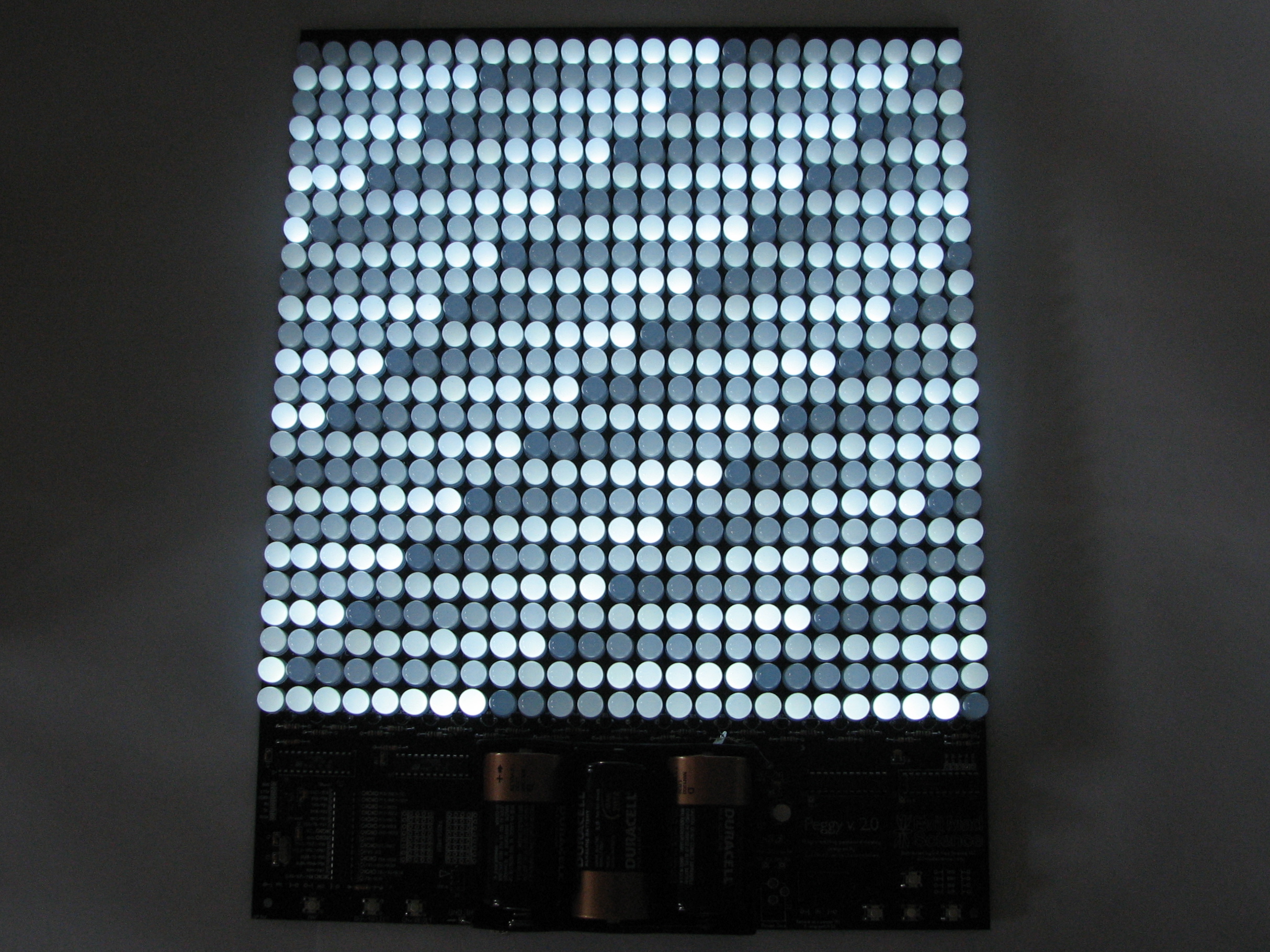
peggy2_GrayTest.pde: A simple application that demonstrates running a Peggy 2.0 display with 16 levels of grayscale. (Pictured above, on a display with 10 mm white diffused LEDs.) It’s slow software PWM and doesn’t leave much room for animation, but isn’t it cool? You could probably put your picture on Peggy and hang it on the wall. :)
peggy_life.pde: Conway’s life application; a more complex and computationally intensive routine with interactive editor (i.e., drawing program) and display refresh routines built in.
AVR-GCC Examples
Some code examples meant to be run with the AVR-GCC toolchain and an ISP programmer
peggy2.zip: Default firmware; lights LEDs uniformly. Good to test for damaged LEDs, should that become necessary. Presents two unsigned int arrays that can be modified to change what’s on the display.
peggy2_Sweep.zip: Simple example showing one row and then one column lit at a time.
Peggy2Life.zip: Conway’s life application; a more complex and computationally intensive routine with interactive editor (i.e., drawing program) and display refresh routines built in.
(More coming soon!)
It is really Cool, can’t wait to see for more cool projects using this v2 board! Nice work!
The above link ‘peggy2.zip’ is broken. I get the following error message:
<Error>
<Code>AccessDenied</Code>
<Message>Access Denied</Message>
<RequestId>50222503DE021DA0</RequestId>
−
<HostId>
jqEawTJeNnzWfEk7LjDHqB/nyO+/stLFaPG1IKU9uWchTmm5ujuh1RQugvjHIdNn
</HostId>
</Error>
Oops– thanks for catching that. Should be okay now. :)
—
Windell H. Oskay
drwho(at)evilmadscientist.com
http://www.evilmadscientist.com/
Hi Wendell, can you explain to me how i can your Game of Life to my P2.0? I cant download the peggy_life.pde file.
This was one of the reasons i bought P2.0, its first GoL then my own programs, a i do have some ideas.
regards
devries
netherlands
080612
Sorry, the permissions seem to have been scrambled again; I think that it’s working now. (I can download the file.)
—
Windell H. Oskay
drwho(at)evilmadscientist.com
http://www.evilmadscientist.com/
Hi Windell,
prehaps im doing things wrong?
First i open web page
"http://www.evilmadscientist.com/article.php/programpeggy2"
then i select "peggy_life.pde"
then with my right mouse button i select : ‘save target as"
it will result in saving a html page.
If i "open" the pde file in a new page
i get a lot of codes, all behind each other beginning with the text: "* Title: peggy_life Date Created: 3/23/08 Last Modified: 4/28/08 Target: Atmel ATmega168 Environment: Arduino – 0011 Purpose: Drive 25×25 LED array Application: Conway’s Life Copyright 2008 Windell H."
Is this right? And do i have to copy all codes to the arduino software program????
Please your advice, as i cant catch any sleep…;-)
regards
devries
081017
Do not save it as an HTML file, just save the file directly as it is– use the "download" option or "save linked file as…" option if you have one.
Once you’ve saved the file, open the Arduino application and from within that program, open up the peggy_life.pde file.
Don’t copy anything to anything.
—
Windell H. Oskay
drwho(at)evilmadscientist.com
http://www.evilmadscientist.com/
I think, I know what you can do. When the codes show up, copy them and paste them in notepad. The go and save the file with a .pde extension on it. Example: game_peggy.pde
How much time is spent by the arduino just updating the led display?
ie How fast can a program be run in the "background" without disturbing the led matrix?
>How much time is spent by the arduino just updating the led display?
The way that the standard Peggy 2 library is designed leaves this up to you. The screen is only redrawn when you call the command to redraw the screen. That means that you can pause for a moment– leaving the screen off, and devote 100% of your processing time to your application. An example of a very processor intensive routine is our 25×25 game of life that wraps around; when we run at high evolution rates, it starts to get dimmer because we’re spending most of our time computing the next iteration.
There are also alternative versions of the library that use refresh-based interrupt, where a constant amount of the CPU time is devoted to screen redraw; that may be more convenient for some applications.
—
Windell H. Oskay
drwho(at)evilmadscientist.com
http://www.evilmadscientist.com/
I’m new to microcontroller programming (but to other kinds of programming), very interested in trying the Peggy 2, but a little confused about the following things:
1. I’d like to update the display, from my computer, very fast. How fast? Well, at least 1000 updates/sec. [Quick explanation: I’m doing experiments on vision, and I need this much speed.] How fast can I update all the 625 gray levels on the display, if I’m using AVR-GCC.
2. Do I just need a USB cable, or something else? Your page mentions an "ISP programmer". What’s that?
Thanks a lot,
Mark
Sorry, I just realized how stupid I was being in my previous posting. I now realize that there’s a microcontroller actually *controlling* the display (duh), and therefore that it’s not directly controlled by a computer. OK, fine, so let me re-phrase my questions:
1. So let’s say I have a program loaded on the Peggy 2 microcontroller, either using Arduino or AVR-GCC. How fast can this resident program update the display, either a single LED or the whole 25×25 thing?
2. Is there a simple and fast way to trigger such a program (i.e., tell it to start running) from a computer, for example by sending a signal on a USB port?
Thanks again, and sorry for the learning curve,
Mark
The absolute upper limit of how fast the Peggy screen can be refreshed is approximately 4 kHz, although it would take concerted effort to achieve this in practice. Data is clocked out from the microcontroller to the display chips (for a given row) at a rate of 4 MHz. There are 32 bits per row (25 columns, plus a few extra bits to round out even bytes), so the whole row is read out in about 8 microseconds. If we repeat this for all 25 rows, that takes a total of 200 microseconds, and there’s a little bit of additional overhead to "latch" the rows, so the whole screen scans in about 250 microseconds, hence the 4 kHz figure. Monochrome data can go to the display up to 4000 times per second. BUT, it will be difficult to get interesting data ready at that rate, since the processor will be *very* busy with displaying the screen.
Most often, we drive the screen at around 1.5 kHz– Displaying the screen 15 times to represent 16 levels of gray scale, giving a final 16-shade image that can change 100 times per second. This also leaves enough time between display computations to perform computations about what the next frame should be. The input source for data can be internal– using its own computations, from sensors like buttons or the internal analog-to-digital converter channels, or from data streamed over a computer link with I2C.
Now, I suspect that your display requirements are not as strict as you are saying… because if they are, then you should already know that a solution to do what you need is going to cost multiple thousands of dollars. If you really need to display 625 gray levels, you’ll need 625 passes to represent that, and if you really need to change *that* 1000 times per second, that means that you need to completely refresh the whole screen at a rate of 625*1000=625 kHz. That means that you’d have 1.6 microseconds to display the entire screen. Using a 16 MHz AVR microcontroller like we do, you would not be able to achieve this display rate– 1.6 microseconds isn’t even enough time to clock out a single *byte* to the screen. If you went to a 20 MHz processor, you could clock out a single byte in 1.6 microseconds, so if you dedicated a microcontroller AND an 8-bit LED driver chip to for every eight LEDs, you could update each one of them every 1.6 microseconds in principle… but that wouldn’t leave time for necessary overhead of loading data onto the processors. A better approach would be to use (more expensive) LED driver chips that have internal 10-bit PWM, but you’d still be looking at a solution with many (maybe 80) LED driver chips and microcontrollers. Or, you would need to go to a larger faster microcontroller– maybe ARM based or an FPGA. None of these solutions would be quick, easy, or anywhere near as cost effective as the Peggy design.
—
Windell H. Oskay
drwho(at)evilmadscientist.com
http://www.evilmadscientist.com/
I have been looking at the schematics, and I’m trying to figure out how the grey-scale brightness levels are achieved. At first glance, the STP16DP05 chips seem to operate like basic shift registers with binary output. So there must be some kind of funky LED switching going on. Can anyone explain how the brightness of each LED is controlled? Am I correct to assume the frame buffer contains 4-bit brightness values for each pixel, which is converted to some kind of a LED duty cycle in software?
Yes, that’s correct.
See also: http://code.google.com/p/peggy/wiki/Pegg2Wiki16Levels
—
Windell H. Oskay
drwho(at)evilmadscientist.com
http://www.evilmadscientist.com/
I’m wondering about an application I have in mind. If I were to mount six Peggy 2.0’s in a 2×3 array, is there a way to aggregate them into a 50×75 matrix and program it collectively, or would each Peggy 2.0 be it’s own "island?"
Each has its own processor, so they are generally independent. You could stream data to all six at the same time, or if running off the internal memory only, send a sync signal between them to keep them in lock step.
—
Windell H. Oskay
drwho(at)evilmadscientist.com
http://www.evilmadscientist.com/
Is the code available for the radiating rainbow animation from a moving point seen on youtube? If so, where can I find the link. Thanks.
Yes, that project is here, complete with source code. :)
—
Windell H. Oskay
drwho(at)evilmadscientist.com
http://www.evilmadscientist.com/
So is it possible to replace the microcontrollers in an array of Peggy 2’s with an external controller/computer? Or, can you interface a computer with those microcontrollers in an array so that the array acts like one huge board? For example, using the Peggy 2 RGB to display ripples, such as you would find on the surface of water when it rains. Do I need an engineering degree to be able to do this? :)
Peggy 2 has an available "I2C" AKA "TWI" interface. This is a multipoint serial interface, over which you can send data to multiple Peggy 2 boards. You can either send full-frame data or just commands that rely on the on-board microcontroller to draw different things on the screen.
Not much electrical engineering knowledge would be needed– the hookup is easy– but programming experience would be helpful.
—
Windell H. Oskay
drwho(at)evilmadscientist.com
http://www.evilmadscientist.com/
CAN I DOWNLOAD ARDUINO STUFF ON WINDOWS VISTA?
Yes.
—
Windell H. Oskay
drwho(at)evilmadscientist.com
http://www.evilmadscientist.com/
Hi
Im new to this but have a particular project in mind and want to know what is needed before purchasing one of your units.
At the top of this (http://evilmadscience.com/tinykitlist/75-peggy2) EMS page there is a picture of the peggy displaying an image of a person.
Is this source from video?
I want to know what I need in order to get a peggy to display video like in that picture.
My basic idea is having a camera signal live feeding into the peggy.
Is this possible?
See this article for more information about that.
—
Windell H. Oskay
drwho(at)evilmadscientist.com
http://www.evilmadscientist.com/
Are there any future plans to have a Peggy upgrade to support 10mm diffused RGB leds in the near future? I’d like to get the best of both worlds of maximizing led real estate with both monochrome and color displays, if possible.
Anyways, this is a really cool project – thanks, EvilMadScientist!
>Are there any future plans to have a Peggy upgrade to support 10mm diffused RGB leds in the near future?
No… if and when we build an RGB version, we probably won’t be using diffused LEDs, for somewhat subtle reasons.
—
Windell H. Oskay
drwho(at)evilmadscientist.com
http://www.evilmadscientist.com/
I want to know how long the Peggy can last on the batteries. I found a similar led board (with less multiplexors, and leds) running with MAX7219 that would only run for 8 to 12 hours if it were converted to run on batteries. Logic says that either this needs to have its batteries replaced every day or two, or my math is waaay off.
The battery life depends *very* strongly on what you’re running, how many LEDs, how bright, and so on. Lifetimes from 24 hours to a couple of weeks are possible, depending. If you want to leave it on for long periods, a plug-in power supply is a must.
Windell H. Oskay
drwho(at)evilmadscientist.com
http://www.evilmadscientist.com/
I have returned to programming my Peggy 2.0 but have lost the USB-TTL cable. The only ones I can find are the ones with six pins all in one row, but the Peggy needs two rows of three. Is there a source for that cable?
I tried a TinyUSB with the Arduino environment but it failed to connect.
>I have returned to programming my Peggy 2.0 but have lost the USB-TTL cable.
>The only ones I can find are the ones with six pins all in one row, but the Peggy
>needs two rows of three. Is there a source for that cable?
>
>I tried a TinyUSB with the Arduino environment but it failed to connect.
It sounds like you’re confusing the different types of programming interfaces:
* The USB-TTL interface is the one that has a 1×6 connector.
* The ISP interface has the 2×3 connector.
I’m not familiar with any 1×6 ISP connector, so I’m not sure what programmer you’re referring to.
If you want to use the Arduino environment directly with the USBtinyISP programmer, it still needs to hook up to the 2×3 connector as per usual, and you can follow these instructions:
http://www.arduino.cc/en/Hacking/Programmer
Windell H. Oskay
drwho(at)evilmadscientist.com
http://www.evilmadscientist.com/
Problem solved. You were right that I had the connectors confused. But the real problem was that I built a new TinyISP and forgot that I had to short resistors R6 and R7 to get it to work with Peggy. Once I did that I am up and running again.
Hey Windell, I’m planning to use the Peggy2LE kit to build a volumetric display. I’m struggling a little bit with my memory and timing calculations. I was wondering if you could help me out.
To get the volumetric display looking smooth, I’m anticipating I need to update the peggy display @ ~20Hz. I have not considered using greyscale yet. So that 20Hz is just flat out some leds are on, .05 seconds later, some different leds are on. From the specs that I’ve looked at, that should not be a problem correct?
The more worrisome area seems to be the memory. If I want to do a 5 second animation @ 20 Hz, that is 100 frames that I need to store on the microcontroller. Each frame needs 625 bits (this is again assuming no greyscale, just an on/off bit for each led). That is 6,250 bits. Getting pretty memory heavy. Am I calculating this the right way? Also, how much memory does this microcontroller have?
Thanks for your help.
I would suggest checking out (and posting your question in) the EMSL Forums, specifically the Peggy Support Forum: [link:]http://www.evilmadscientist.com/forum/index.php?forum=14
I am having a lot of trouble with the Peggy 2.0 programs and Arduino.
First I download the Arduino software and uncompressed the file with no problem, then I downloaded the Peggy2Lib_0.30b which is when the problems start. I had a problem trying to get the Peggy2Lib_0.30b to uncompressed and I found another way to do it by deleting the Mac file that I had to download with the Peggy2Lib_0.30b then Extract the files. After that I opened the Arduino folder and put the uncompressed Peggy2 folder with the Arduino Library. Next I opened the Arduino software went to Examples and didn’t see the Peggy2 folder I put in there but when i went back to the Arduino folder it was still there. With that being said, I wanted to know why, after carefully following the directions posted on this page (http://www.evilmadscientist.com/article.php/programpeggy2) I still wasn’t able to find the folder in that location in the Arduino Examples Library?
Even after the problems I had with file placement, I found another way to put the Peggy2 folder in the Arduino program by going to the main Arduino file (in My Documents) and placing the Peggy2 folder in it. Then opened the Arduino program again and clicked on (File), (Open), and clicked on the Peggy2 folder and all the Peggy 2.0 programs where inside and I clicked on the Gray_Sketch_Peggy2_0_ then the compile button in the Audrino program and it compiled with no problem. I was extremely relieved to see that my alternate method worked until I tried the PeggyWriter_Hello and it tried to compile in the Arduino program and got an error message (I couldn’t copy and paste it here but it was sayin the file wasnt in the directory along with a lot of other stuff and had this {Peggy2 frame1; // Make a frame buffer object, called frame1} highlighted. I tried many of the other Peggy2 programs and got the same or nearly the same error message for them all. the only three that would work were:
1. Gray_Sketch_Peggy2_0_
2. Game_of_Life_Peggy_2
3. sketch_nov08a
Even after scouring the web trying to find out if i could fix it I couldn’t find anything so can someone PLEASE help me?!?!?!?
>I am having a lot of trouble with the Peggy 2.0 programs and Arduino.
That does not sound like it’s actually the case. Rather, it sounds like you’re just having trouble installing the library. You will know that the library is installed when "Peggy2" shows up in your "Examples" menu. If it does not appear there, the library is not installed.
Please refer to the Arduino instructions on how to install a library, following the instructions on this page, under "contributed libraries": http://www.arduino.cc/en/Reference/Libraries
Blog comments are not an appropriate location for tech support questions. If you need additional assistance, please instead post in our support forum:
http://www.evilmadscientist.com/forum/index.php?forum=14
Windell H. Oskay
drwho(at)evilmadscientist.com
http://www.evilmadscientist.com/