


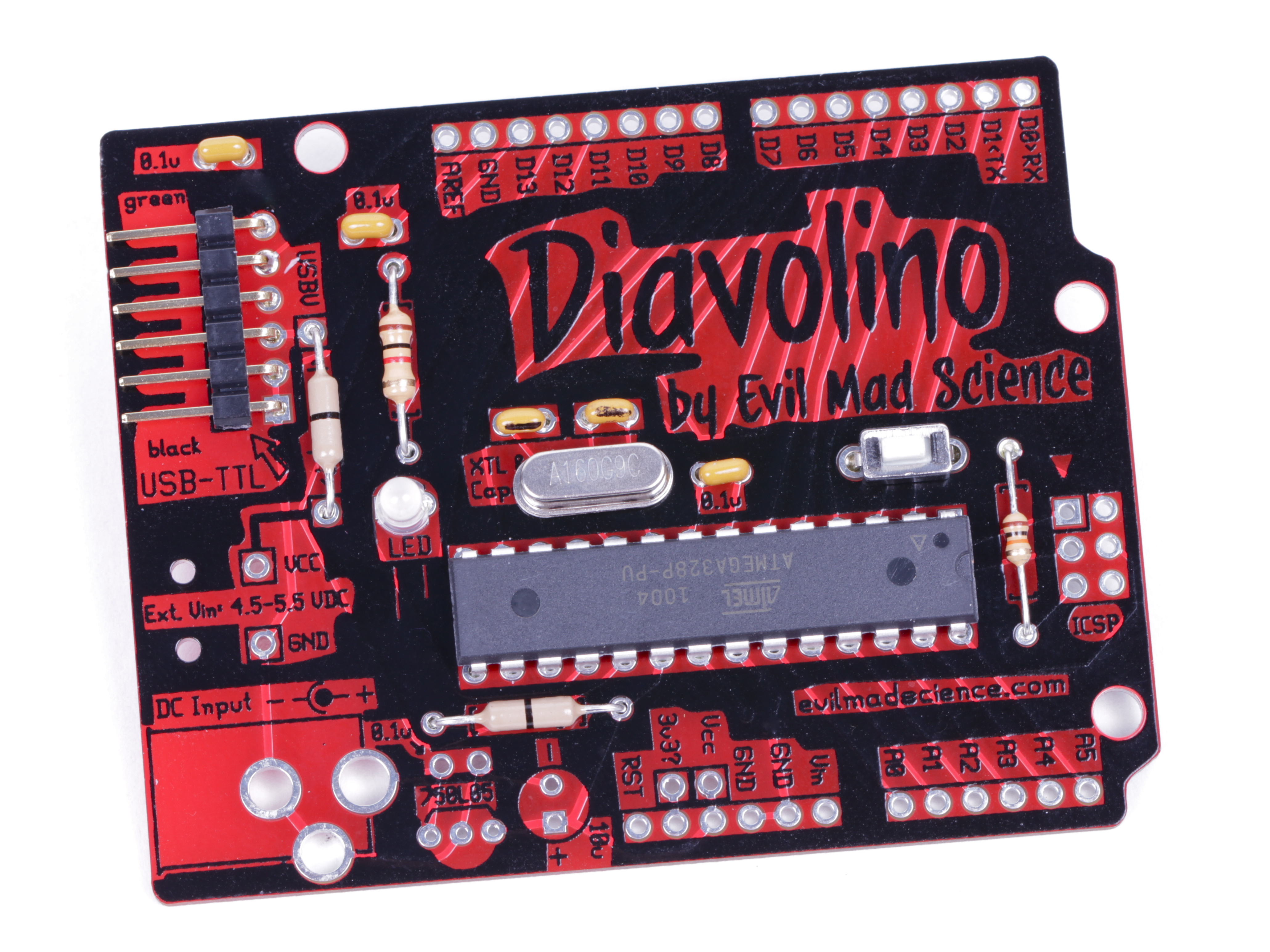
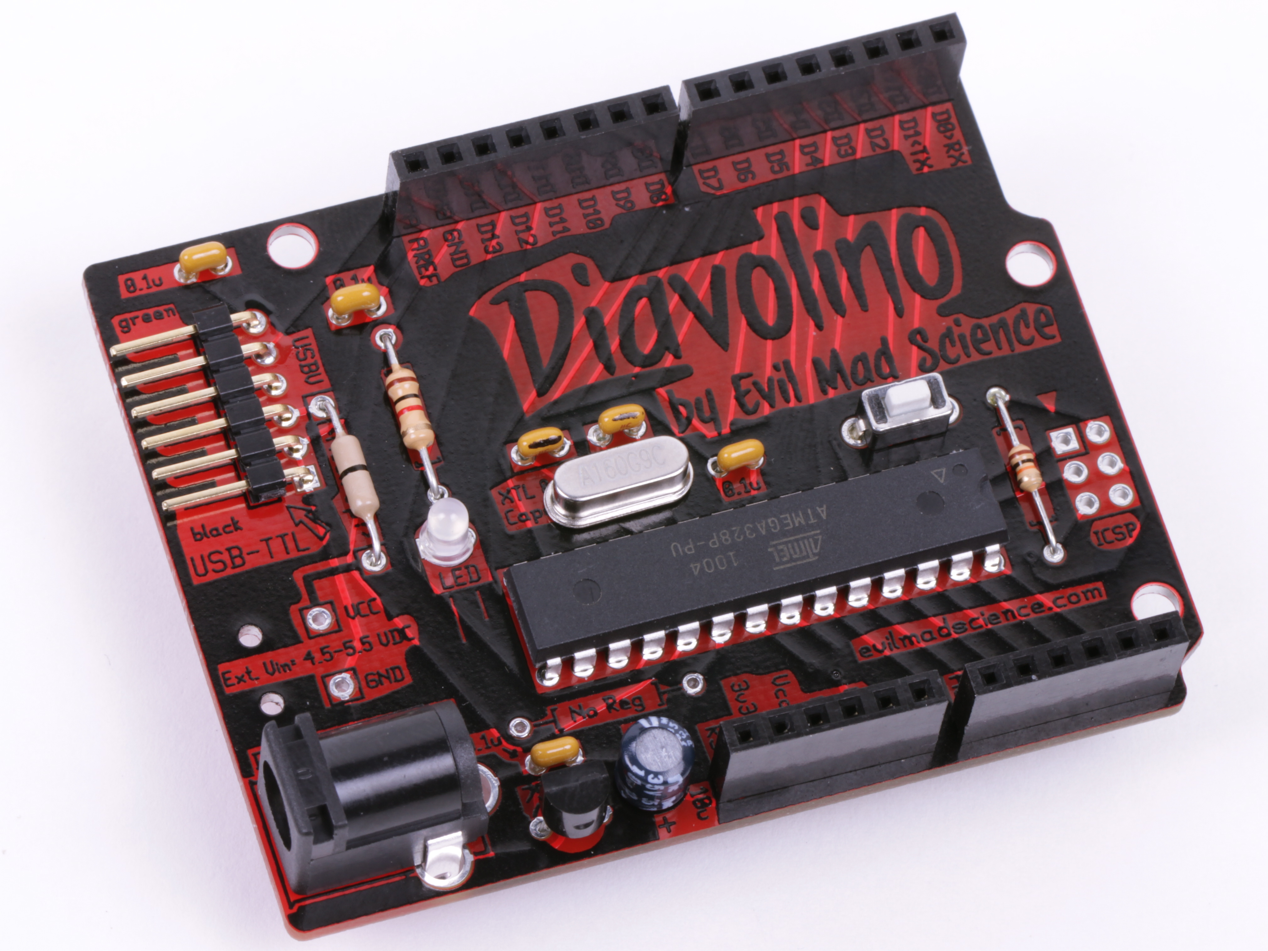
Say hell-o to Diavolino. Yes, it’s yet-another Arduino compatible board, but it’s cheap and kind of neat. Simplified design, rounded corners, and shiny. Open source kit. You can get one at our store here.
We designed this primarily in response to local need in our San Francisco hacker community for low-cost boards for teaching.
In many ways, this project is reminiscent of and complimentary to our ATmegaXX8 target boards, which are low-cost, simple design circuit boards for programming AVR microcontrollers through an ISP connection. And while you can add one, those boards don’t have a place to put a USB-TTL cable. And so here we are.
The design is like what you’d get if you bred the Ardweeny from Solarbotics with the 5 V Arduino Pro from SparkFun. It’s designed as an open source, through-hole soldering kit, with the “Duemilanove” form factor.
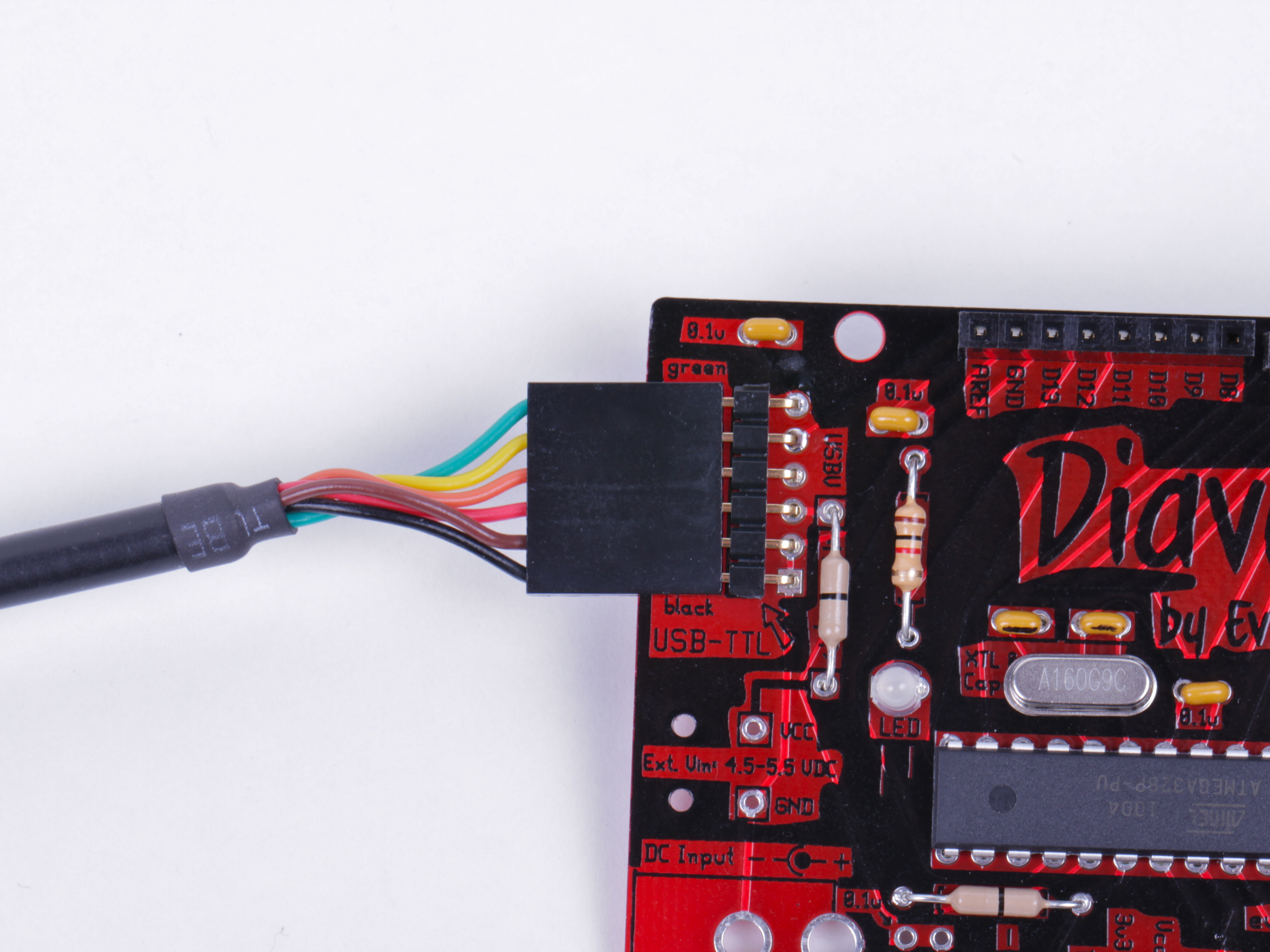
It has a low-profile design– at least as far as through-hole goes. The tallest component is the 3 mm LED, and there are smaller ones out there if that’s a problem. As with many other boards of this type, it uses the “bare bones” method, removing the FTDI USB chip from the board in favor of
using a USB-TTL cable.
And it is *really* bare bones– more bare bones than a Bare Bones Board, to be precise.
It has a reset button, the LED, auto-reset parts, decoupling caps, (etc.), plus wire jumper locations for optional power by USB-TTL connector and regulator bypass, and a crystal oscillator, but no regulators by default.
And… it has flames.
But, here’s what you won’t find on Diavolino:
- The USB interface chip– again, that’s why you need the cable.
- Advanced power management. Please provide power to Diavolino from one source at a time: battery, USB, or plug-in power supply.
- A separate 3.3 V regulator. Shields and accessories that require separate 3.3 V power may need assistance to work correctly.
Additionally, it’s worth noting that the 6-pin ICSP programming header is not positioned to correctly fit “hermaphrodite” shields that have both male and female headers on the bottom. (It can be wired up, of course.)
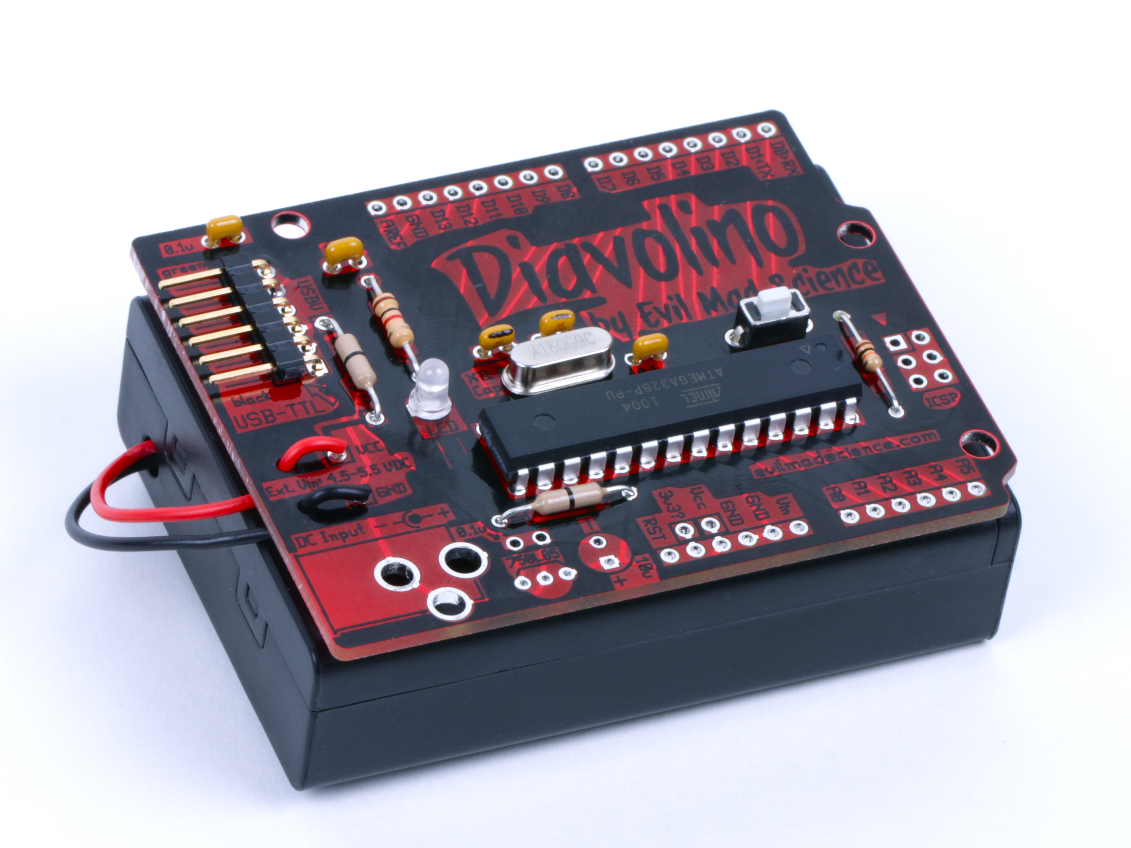
The board has strain-relief holes (Dale Wheat‘s trick) for battery wires, and lends itself well to this configuration: The board plus a 3xAA battery box and a strip of double-sided foam tape. Pretty darned portable.
With a bunch of optional components added– side sockets, power jack, little regulator — it starts to look a little more recognizable.
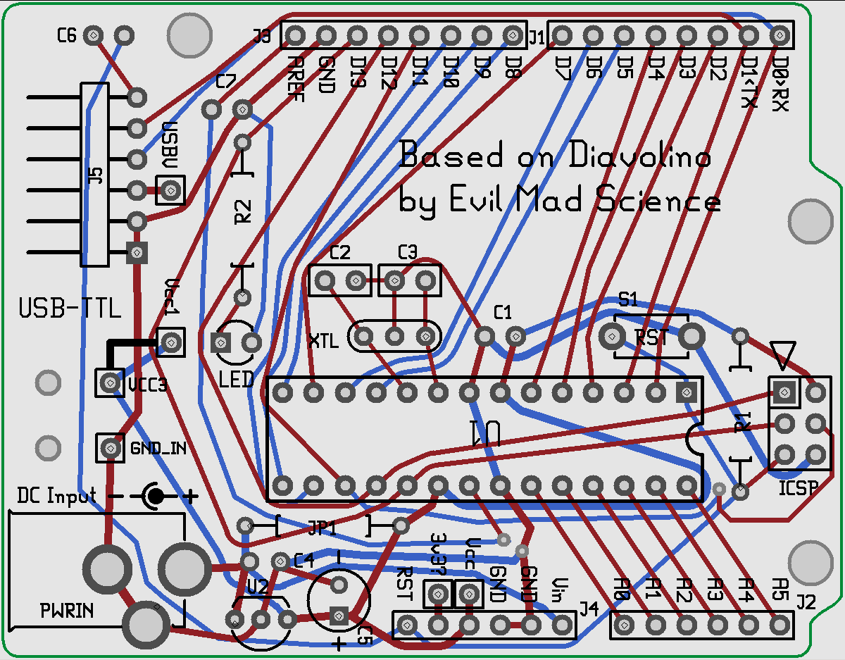
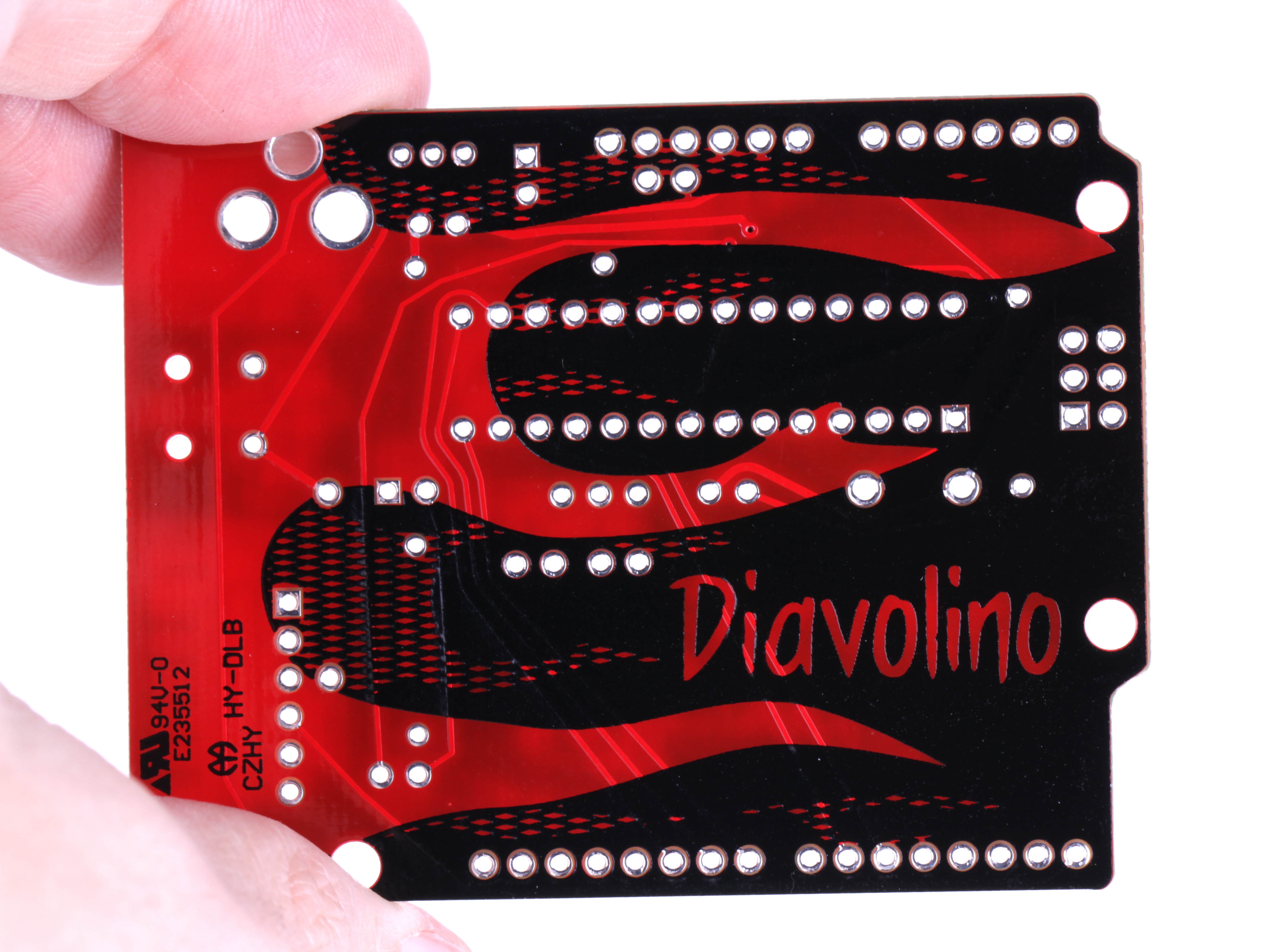
The circuitry was designed in gEDA, and we’ve released the PCB design files as a “reference design” that peels back the artwork so that you can actually see the connections and the component labels– it makes a much better complement to the schematic, and you can download the files from the documentation links below.
The Diavolino is available at the Evil Mad Science shop.
- Documentation links:
- Download schematics here
- quick start card
- Detailed instructions(8 MB PDF)
- PCB design(ZIP archive, for use with gEDA)
- Need additional help? You can ask questions in the Diavolino Support Forum
It would be nice to have additional hole/TH contact pad next to 3.3V, connected to ground, to have possibility to solder additional 3.3 regulator. I have used this approach few times by soldering 0.1 uF 0603/0805 smd caps directly to TO-92 package leads close to regulator’s case to stabilize it.
Hey, great idea, and I love the flames. It’s a nice touch! Great price too.
But I have to comment on the trace routing. Why so messy? Where are the nice straight lines and 45 degree bends? Was this done on purpose? I know it’ll work just fine, of course. Maybe it’s just a pet peeve of mine.
I normally route boards by hand. However most of the traces on this board were routed using a topological autorouter that is under development for gEDA. The software is not yet stable and only works well in fairly limited circumstances– and this board was small enough that it could be used as a demo project. I had to make few fixes (the straight lines that you see) but other than that the board consists of neat, optimal curves.
You might find it messy, but to me the topological autorouter is a thing of pure mathematical beauty.
Windell H. Oskay
drwho(at)evilmadscientist.com
http://www.evilmadscientist.com/
Huh, interesting. It really does look like a combination of old-school hand drawn art and an autorouter. I still can’t say I enjoy the "look" of it, but I do appreciate the math behind it. ;)
Windell has already replied, but when I first saw it I assumed it was part of the "from the pit" design, to compliment the flames.
Remember that *old* boards were routed by hand, and that straight lines were unnecessary. I’ve seen some lovely flowing lines on old power supply PCBs…
This is great news. Very, VERY useful, and affordable.
Ordered some to replace the Duemilanoves: Diavolinos come with no pins so I can solder the wires directly, making it all permanent and leaving the Duemilanoves for prototypes again.
It’s a good alternative to the arduino pro with a great price. Gotta love the black/red board and overall style!
I have a 3.3V FTDI cable from another project. Can I use it to program the Diabolino?
That’s Diavolino, not Diabolino. :)
Yes, you can use it to program the board. However, the board cannot be *powered* from that 3.3 signal, and so you’ll need to provide separate power to it.
Windell H. Oskay
drwho(at)evilmadscientist.com
http://www.evilmadscientist.com/
Very nice! I love how the traces shine through the red and become part of the design.
I’m a little surprised you didn’t use some of that space where the big logo is to add a little “breadboard” prototyping area – I thought that was such a cool and useful feature of your ATmegaXX8 boards. Then again, you wouldn’t have that space to show off the cool logo… ;-)
We considered it, but by the time that we added the breakout holes on both sides plus labels for all those holes, there wasn’t really room to fit all of the *parts* let alone the word "Diavolino." Just think how much that chip has to move to fit an extra row of holes and labels below it.
In the end we remembered what we were doing– making a simple cheap board –and relented. :)
Windell H. Oskay
drwho(at)evilmadscientist.com
http://www.evilmadscientist.com/
It looks like entirely too much fun…
Hmm. The ICSP connector is not where it needs to be in order to work with some pathological "shield" designs that used it to access "reset" (the zigbee shield being the most common.) I think that includes quite a few "protoshields" that propagate the icsp connector upward.
"optimal curve based routing" will take some getting used to. It looks particularly … disconcerting, somehow.
Ugh. Pathological is correct. That wasn’t on my radar at all; I have not used shields with descenders like that. I’ll have to make a note of this, and move that connector in the next rev. Thanks for catching this, and catching it early. :)
Windell H. Oskay
drwho(at)evilmadscientist.com
http://www.evilmadscientist.com/
Actually, not so pathological… there are shields like the http://www.nkcelectronics.com/nkc-ethernet-shield-for-arduino-mega–duemilanove–diecimila-diy-kit.html that use the SPI signals from the ICSP connector so they can work on both the classic Arduino boards and the Arduino Mega.
Actually, that’s exactly what I’d call pathological.
Those pins were not originally intended to attach to shields. The fact that these shield designers have figured out a way to kludge it to work with Arduino Mega boards does not make it correct, and certainly does not excuse the fact that they are not compatible with the actual sockets on a Duemilanove.
The original idea of Arduino shields was that they connected to the sockets on the side. Every pin of the ICSP connector is also broken out to these sockets; and the fact that the header is populated by male pins– not a socket –should be a pretty clear indication that shields were not supposed to connect to it. That they have done so is a shame– a bigger mistake than the pin spacing in my opinion.
Windell H. Oskay
drwho(at)evilmadscientist.com
http://www.evilmadscientist.com/
Great design over all! Dutifully blogged and added to my attempted all-encompassing Arduino-compatible board spreadsheet.
I’m curious: why no socket for the ATmega, and only a 150mA 5V regulator? And ditto on westfw’s question about the ICSP header, since it seems like there’s room over there. Also… um, any word on Zuccherino?!
Thanks for the linkage and adding us to your big list. (Should I mention that the Bulbdial Clock kit is also a Freeduino?)
>why no socket for the ATmega
We try not to use sockets unless there’s a *reason* to do so. Some of our other kits do have sockets, and some do not. There hasn’t been any evidence– in thousands of kits –that lack of sockets is causing any issues. Part of that is because these chips are tough as nails, and don’t die as easily as chips that we would historically keep in sockets, nor are they easily damaged by soldering.
So, the only valid reason that I can see to put them in a socket is in case someone installs one backwards. That’s also a rare occurrence in my experience. Sockets also encourage people to *try* and take the chip out when something doesn’t work– often ending up with mangled chips, so it’s not clear that they win even on principle. Beyond that, for this specific kit, we get a lower profile and lower cost. We’re selling these boards as low as $9.10 each at our web store; every penny counts.
> and only a 150mA 5V regulator?
We wanted the TO-92 for low profile. There’s also a 300 mA regulator that fits (same type as on the RBBB), but we don’t have them yet.
Now, why not go with a monster regulator? Two reasons. First, higher-power through-hole regulators (e.g., TO-220) are huge. Second: it’s not efficient in any sense to use high-power linear regulators. Think about it: the Duemilanove power jack only works with about 6 V or higher. The Diavolino, by contrast, has an optional jumper across the regulator, so that you can directly power it from a 5 V supply– even a 5 V, 1 A supply (or probably higher), if you need that much. It’s really nice to have that much power, and you get it without burning up your board.
So, we’d definitely encourage you to drive it directly from 5 V. In the less-likely case that you *need* to use a 9V supply, you *can* still do so with a regulator but you probably still don’t need much more than 150 or 300 mA for the chip itself.
>And ditto on westfw’s question about the ICSP header
Again, that totally was not on my radar. The shields that I have seen just have the male headers on the sides. We’ll make it hermaphrodite-compatible in a future revision.
>Also… um, any word on Zuccherino?!
Sorry, no progress since last year’s versions for the CF6k. But thanks for the reminder; I should update those and release them, shouldn’t I. :)
Windell H. Oskay
drwho(at)evilmadscientist.com
http://www.evilmadscientist.com/
re: socket for chip: I bought the kit and it sat in a corner for a few weeks. I put it together this evening and came looking for a reason why I was getting the "no sync" error when downloading the blink sketch. I came to this comment; looked at my board; and finally noticed the chip was in backwards. This after making a note about orientation of the chip; after soldering in the sockets the correct way (the 14 pinners I use have a notch at the top); and even reading the build instructions with the bold, attention grabbing graphics clearly stating the chip is upside down. So, I’m happy I put the socket in. My original intent in socketing the chip is to be able to pop it out and move it to some other board. But since I also just finished putting together the ISP shield , this reason was moot. So it came down to habit, but I’m glad I did. Anyway, the lights are blinking now – red of course.
Any idea where I could find a red-colored IC socket to complete this masterpiece?
Digikey?
You said this is an open source design? Not to be rude, but it would be great to get the GEDA files. :) haha.
…I just ordered one from you guy’s, but it would be great to get cheaper boards (ie. just the boards), and since you guys dont sell just the boards yet, I need the files so i can produce my own.
…also on a related topic.. Is GEDA suitable for easy use yet? I tried it once, but found it to not be to my liking. I’ve since only used EagleCad, but I’m interested in GEDA again.
As we said pretty clearly, the design files and instructions will be posted next week, when kits begin shipping.
Also, our web store does sell the boards alone pretty cheap: $5 each or or 10/$36.
(You won’t do better than that unless you fab them yourself or make quite a few of them.)
http://evilmadscience.com/partsmenu/183
We find gEDA quite easy to use, but it’s largely a matter of taste.
Windell H. Oskay
drwho(at)evilmadscientist.com
http://www.evilmadscientist.com/
Awesome looking board!
Cheers from Canada,
ao (http://www.technoetc.net/blog)
The zip file doesn’t have the footprints library and / or the gerber files. Hence the design can’t be reproduced as-is.
-Arduino Reviewer
That’s quite a conclusion to jump to– a very misleading and inaccurate one. The footprints are fully contained within the PCB file, and can be extracted to individual files if need be. But, generally speaking, you don’t need to do that. Just open up the file and start using it, or just select export (to gerber) from the menu.
Windell H. Oskay
drwho(at)evilmadscientist.com
http://www.evilmadscientist.com/
In that case the references should not be included in ref-design files
"elements-dir ../footprints
component-library ./symbols"
it could be misleading. A proper readme would avoid any "jumping" to conclusions.
It looks great!
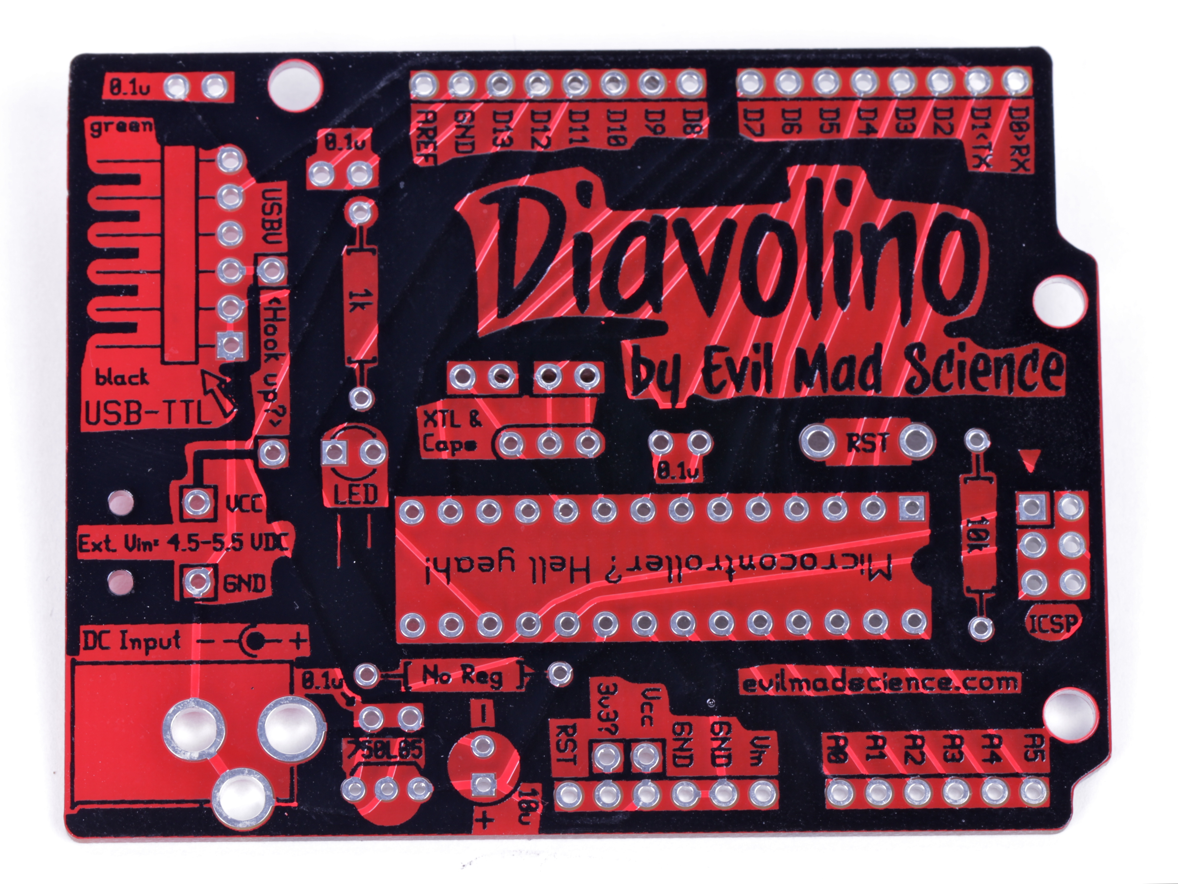
How does it work with the silkscreen, the paint is nice and thick not thin like normal silkscreen.. it looks like the text is the same paint as the soldermask.
Is there a manufacturer that uses the same paint for soldermask as silkscreen? or can you ask for that when you order?
It’s actually normal silkscreen– just *a lot* of it.
Windell H. Oskay
drwho(at)evilmadscientist.com
http://www.evilmadscientist.com/
Just got my Diavolino kits in the mail on Friday, right before the long July 4th weekend! I played with electronics a lot in high school and college, but I haven’t been active in electronics for the past 20 years (but really wanting to get back to it).
Well, today (Saturday) I built a Diavolino in about 1-1/2 hours (not bad considering how long it’s been since I last soldered). Plugged one end of the FTDI cable into the board, the other into the PC, waited for the drivers to automagically load, and a few minutes later, I had the Blink sketch running.
It’s going to be a fun weekend :). Thank you, Evil Mad Scientists, for giving me the incentive to start my new old hobby again!
Hi,
My Diavolino arrived today, and so far so good.. Only problem I find is to upload a sketch, I have to unplug and plug back in my USB-TTL cable (also brand new) and hit Upload straight away, otherwise I get a sync error in Arduino0018.
Using the onboard Reset button before upload didn’t seem to help.
My Duemilano uploads alot faster and reboots automatically it seems.
Any guesses on if it’s the FTDI Cable, the Diavolino, or is this just the way it is?
Cheers
Dargs
From the Forums, [link:]http://www.evilmadscientist.com/forum/viewtopic.php?showtopic=3270:
Try adjusting your port settings to end the pain: Device Manager – Comm Ports – USB Serial Port – Port Settings – Advanced button – Set RTS On Close.
Hope this helps!
squall_line has the right answer (thanks!)– And, please visit our Diavolino Support Forum to ask tech support questions– the comments section to the blog article isn’t very conducive to back-and-forth discussion. ;)
Windell H. Oskay
drwho(at)evilmadscientist.com
http://www.evilmadscientist.com/
I really like my Diavolino, more than one will soon find homes in more permanent projects. The best thing in my opinion is the concept of only paying for what you need, with regards to interface, power supply and so on. So happy I wrote about it: http://wp.me/pQmjR-HO
Keep up the great work
john
Thanks John, and thanks separately for the nice review!
(And *very* sorry for skipping your jumpers– please contact us through the web store if you’d like us to send you a set, or just tuck extras in with your next order!)
Windell H. Oskay
drwho(at)evilmadscientist.com
http://www.evilmadscientist.com/
You have a short between ‘Black’ and ‘Brown’ on the FTDI connector. Many of us @ tT were using the BUB’s from Modern device which forwards the 3.3v logic on the ‘Brown’ connection. Other formats specify it as no connection, or are using it for 3.3v logic as well.
This is caused several of our FTDI chips to get VERY hot. Luckily we caught on and unplugged them before any damage had been done.
The best fix we have found for this is to cut and remove that pin from the Diavolino board. Still it should have never been designed that way, and I would hate for anyone to burn up their FTDI over a dumb mistake.
Other then that we love the Diavolinos. Maybe it’s time for a v2. :)
We normally refer to intentional wiring between two points as a "connection," not a "short," but thank you for the report about the conflict with the BUB. Probably the best short-term solution is to cut that pin on the header. We’ll certainly consider removing that connection in the next rev, but I’m curious why the BUB is designed that way– it probably won’t work with any of our kits.
Windell H. Oskay
drwho(at)evilmadscientist.com
http://www.evilmadscientist.com/
I assumed (incorrectly it would seam) that it was an unintentional wiring. I was basing this on the routing of the rest of the board (which works great, just sets off the OCD in a few of us).
The bub (linked below) works great (aside from this problem), and is a standard FTDI chip. They may not have the standard pinout (not sure what that line should be tied to, it looks like it varies from place to place), I just thought it should be brought up that in some instances it may cause problems or hardware failure. A quick search looks like there may have been a few other people with related problems.
http://shop.moderndevice.com/products/usb-bub
As far as I can tell this is mainly a problem with the Modern Device BUB paired with the Diavolino, and only if you have your BUB header on a few select rows.
The "Adafruit ftdi friend" sold at EMS has that pin listed as CTS. Not sure if it is good practice to pull it low, but looking around at several other ftdi boards it is not required.
Thanks again for all the you guys do here, no disrespect is intended. We have followed you for years and try to order from you guys w/e we can. I will also note that this is not indicative of the otherwise very high (and very OCD friendly) products you have in your store.
It is a very interesting issue, and again, I do thank you quite sincerely for pointing it out. Our Arduino-compatible kits that use the FTDI interface (Diavolino, Bulbdial, Peggy 2, and Meggy Jr RGB) all use this pinout, and do work very well with all of the other FTDI breakout boards that we have come across.
Honestly, this is the first that we’ve heard of an issue like this– after what is (by any standards) a very large number of kits. It may also be worth noting that ours are not the only Arduino clones that have this wiring.
The BUB has an unusual layout that does make certain assumptions about the target board. We will try to eventually revise all of these kits to be compatible with it– so long as we don’t come across any reason *not to,* but it will take some time.
Windell H. Oskay
drwho(at)evilmadscientist.com
http://www.evilmadscientist.com/
Since the original cables that it’s meant to be compatible with lists that as the CTS input, I’m more comfortable with it being a ground than an extra voltage out by default. Having a 3.3V out on that line would be telling someone looking for CTS that it’s never okay to send anything.
http://www.ftdichip.com/Support/Documents/DataSheets/Cables/DS_TTL-232RG_CABLES.pdf
The BUB is designed to be “flexible” and setup differently for different applications (all of the default configurations in the instructions show CTS unconnected) so I think redesigning the Diavolino for a non-standard setup would be a bit unnecessary.
I think I am, therefore I am… I think
Of course, looking closer at the cable, the active-low CTS can be changed to active-high, but since that isn’t the default, I’m still happier with ground.
I think I am, therefore I am… I think
According to the BUB instructions, it seems that the only way they show the connector connected, that pin is unconnected. So you either have to jumper to it, or install the connector farther inside than the diagram shows. While you could leave it unconnected (as the BareBones seems to) in a revision, since the default configuration looks like it would work (and LadyAda’s Boarduino also has it grounded) I think there needs to be a more serious problem before revising it for that situation.
I think I am, therefore I am… I think
Yes. Having looked at the BUB instructions, it’s clear that the Diavolino *is* compatible with the BUB, except that you’ve wired up your BUB such that it is no longer compatible.
Windell H. Oskay
drwho(at)evilmadscientist.com
http://www.evilmadscientist.com/
My usb-bub is wired with 3.3v (from the FTDI’s internal regulator) to the "brown" wire’s pin.
Little board got rather hot before I figured out what was up!
No damage done, but a fair warning on the product page or an insert would be nice.
The usb-bub I’m using is 100% normal wiring. I actually have a second connector hand-wired off to the side that leaves the brown wire’s pin disconnected (it puts the 3.3v regulated output on the 5v/VCC wire), so I’ll be using that for the Diavolino.
Other than that minor issue (nothing died, can’t be that serious right?), I love the board!
I agree, my suggestion is that is may be better to simply leave it as a NC. Is there any reason to tie it to ground vs not connecting it at all?
By default (for the standard FTDI cable) that pin is "CTS", or Clear To Send. It’s a signal line that you drive low (ground) to tell the computer it’s okay to talk to you. So running a positive voltage to it is like saying "Don’t talk to me", and leaving can be read the same way… If the system is watching the CTS.
Running it directly to ground that way is basically telling the computer "Talk to me whenever you like".
I think I am, therefore I am… I think
Thanks karlgg,
Do you know of any situations where the host computer *does* monitor that line? I’m wondering what (if anything) will break if we break that line.
Windell H. Oskay
drwho(at)evilmadscientist.com
http://www.evilmadscientist.com/
At the moment, I have no clue, since that would be handled by the FTDI chip internally (none of those lines technically make it to the computer through the USB – the chip does all the thinking). I don’t currently have anything that wasn’t designed by you or LadyAda, so all my devices are grounded on their CTS…
I’ll check around and see what I can find on the topic, but for now you’re following the specs as I’m aware of them. I might hook up an AVR on a breadboard to play with "raw", or maybe it’s an excuse to buy more "research" items. :)
I think I am, therefore I am… I think
As near as I can tell Arduino-ville doesn’t use CTS for anything so from their end, it’s completely extraneous. We don’t use handshaking at all (which I should have realized earlier – since we use the RTS for the software reset).
Other things using the FTDI like the Adafruit XBee adapter have both RTS/CTS connected as normal handshaking lines, since the cable is meant to be a general serial port that might need those. The BUB six-pin connector has a definite Arduino leaning, as the pinout uses DTR instead of RTS (so the "RTS on close" is probably unnecessary) and skips the CTS entirely.
So it looks like leaving CTS unconnected would probably not cause much ruckus.
However, I’m still for leaving it alone. Not only do the FTDI-cable designs of yours, Adafruit, SparkFun (including the Lilypad) and Spikenzie (on my brief search) all have them set to ground … But that’s what an active-low CTS ought to be stuck at, if it’s going to be stuck at anything.
I think I am, therefore I am… I think
A thought on the CTS pin: Rather than wired straight to ground or left NC, why not pull it low with a 10k or 1k resistor? That’d still pull it low in case an application actually uses CTS, but it wouldn’t fry USB-BUBs. Costs a touch more, but not that much.
Allegedly the Arduino is a power-piggish sleeper compared to the raw chip’s potential. Since the Diavolino doesn’t have this by default, does this make the D’lino a bit more power/sleep friendly? (Likewise, would adding the regulation ‘ware on it make it less so?)
(I edited your comment to fix the broken links.)
Yes, the usual Arduino design is remarkably power inefficient. If you have 9 V input, and regulate that down to 5 V, you’re just burning up 4 V (at whatever current) as heat. Diavolino (without the regulator) is a much better choice if you’re looking to run on batteries.
Windell H. Oskay
drwho(at)evilmadscientist.com
http://www.evilmadscientist.com/
Just noticed you don’t have a reverse polarity diode on your DC Jack input. Most power supplies do have center positive, but some don’t. Maybe consider adding this for a future revision, even if it’s a normally jumpered location.
Great looking board! I love how the red soldermask is translucent, giving a great contrast to the opaque silkscreen.
Reverse polarity protection has a steep price, usually about 0.7 V– enough to make it so that you can’t actually run with a 5 V power supply. (Since the AVR requires 4.5V – 5.5 V to run at 16 MHz.)
The Diavolino is very intentionally a stripped down version that requires care in power supply selection. If you think that there’s any chance that you might grab the wrong power supply, we’d definitely recommend going with a brand-name Arduino instead. :)
Windell H. Oskay
drwho(at)evilmadscientist.com
http://www.evilmadscientist.com/
…Besides, if you use the low dropout reg supplied in the power "expansion" pack (TL750L05CLP) that has reverse voltage protection built in, which would protect you at least from plugging in a "centre negative" wall wart (they do exist!!). If you burn out your board soldering a power pack in backwards then maybe you need more help than a diode will afford :)
Just received mine, put it together and powered up. The LED blinked away reassuringly (I presume the blink sketch is pre-loaded for this purpose and I haven’t got a 2nd hand one!)
This is one nice board :)
Hi. would you recommend it for arduino "beginners" ?
It depends where you want to go with your Arduino projects. There’s nothing particularly more difficult with this than with a regular Arduino– if you like to solder –but you’ll be up and running a little faster with a brand-name Arduino because it comes ready to use.
Windell H. Oskay
drwho(at)evilmadscientist.com
http://www.evilmadscientist.com/
I’m confused on the TTL.
I have USB to TTL adapters that only break out TX,RX, and GND. You’re cable has more. Possibly you are also using power? Will my cables work to program this chip?
Chris
This cable does carry 5 V, but the most important thing is that there’s one more signal there that "auto resets" the AVR, triggering its bootloader sequence. It’s not needed for serial communication, but just is a handy step for reprogramming the MCU through the cable. If your cable only has TX/RX, you’ll need to manually press the reset button when reprogramming.
Windell H. Oskay
drwho(at)evilmadscientist.com
http://www.evilmadscientist.com/
Thanks for the response. After I press the reset, about how long do I have until avrdude needs to transmit?
Also, will the Zif socket fit? Could use as programmer.
Chris
Typically the bootloader is configured for a 2 s delay. You can change this, of course.
A ZIF socket will not fit. You might be interested in these, however.
Windell H. Oskay
drwho(at)evilmadscientist.com
http://www.evilmadscientist.com/
Thanks. Yea, I’m going to get a few of those too. I’ve got a project I need to complete and the enclosure is an aluminium hammond box that is just slightly bigger than a business card. I’ve got a serial AVR ISP programmer I bought about 6 years ago. Unfortunately it is 10 pin.
Have you thought about a kit and board that creates a programmer? Not the shield kit but a single PCB with the 328 as the processor and a zif socket for the target.
Chris
>Have you thought about a kit and board that creates a programmer?
>Not the shield kit but a single PCB with the 328 as the processor and a zif socket for the target.
No; we already have the USBtinyISP kit and the ISP shield kit– no need for additional variants. Also, a bit off-topic here for Diavolino– we do have forums for general-purpose discussion. :)
Windell H. Oskay
drwho(at)evilmadscientist.com
http://www.evilmadscientist.com/
OK I’m trying to get head around the 3.3v on the Diavolino .
So on a "stock" Arduino I guess there is a 3.3v voltage regulator and it can supply this voltage. On a Diavolino I can install a jumper and get 3.3v from the Adafruit FTDI Friend that was included in 5 pack I just got on the mail.
I’m still trying to figure all this stuff out hardware/software wise.
Luckily I used to program for a living so that doesn’t scare me its just the hardware interface I’m trying to figure out.
The Diavolino *does not* provide 3.3 V. IF you have a shield that requires 3.3 V for some reason, you can put it in from the 3.3 V location on the Diavolino.
Windell H. Oskay
drwho(at)evilmadscientist.com
http://www.evilmadscientist.com/