


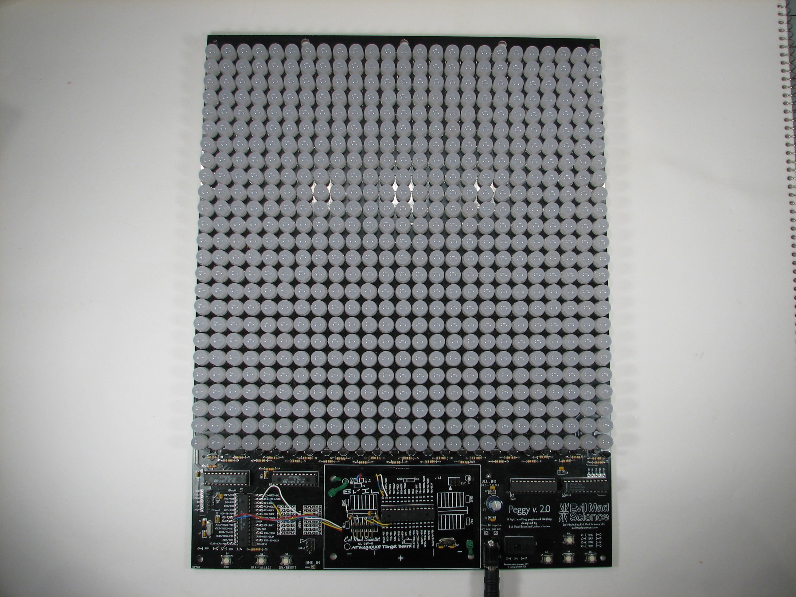
For a while we’ve been meaning to try out Jay Clegg’s TWI-video hack for the Peggy 2, and we must say, it’s pretty nifty. Using this routine, we can take webcam video (e.g., from our MacBook Pro’s built-in camera), sample it in a Processing routine, and send it to be displayed on the 625 LEDs of the Peggy 2.
Some months ago we wrote about Jay’s previous project: sending video to a Peggy 2 with a hardware serial port added.
While that’s pretty impressive, it’s also a bit invasive, since it requires rewiring the Peggy board. The new version of the project streams data to the Peggy 2 microcontroller over its TWI (also known as I2C) interface– a separate serial interface that’s available. An external Arduino board (or equivalent) sits between the host computer and the Peggy as a serial-to-TWI (I2C) converter.
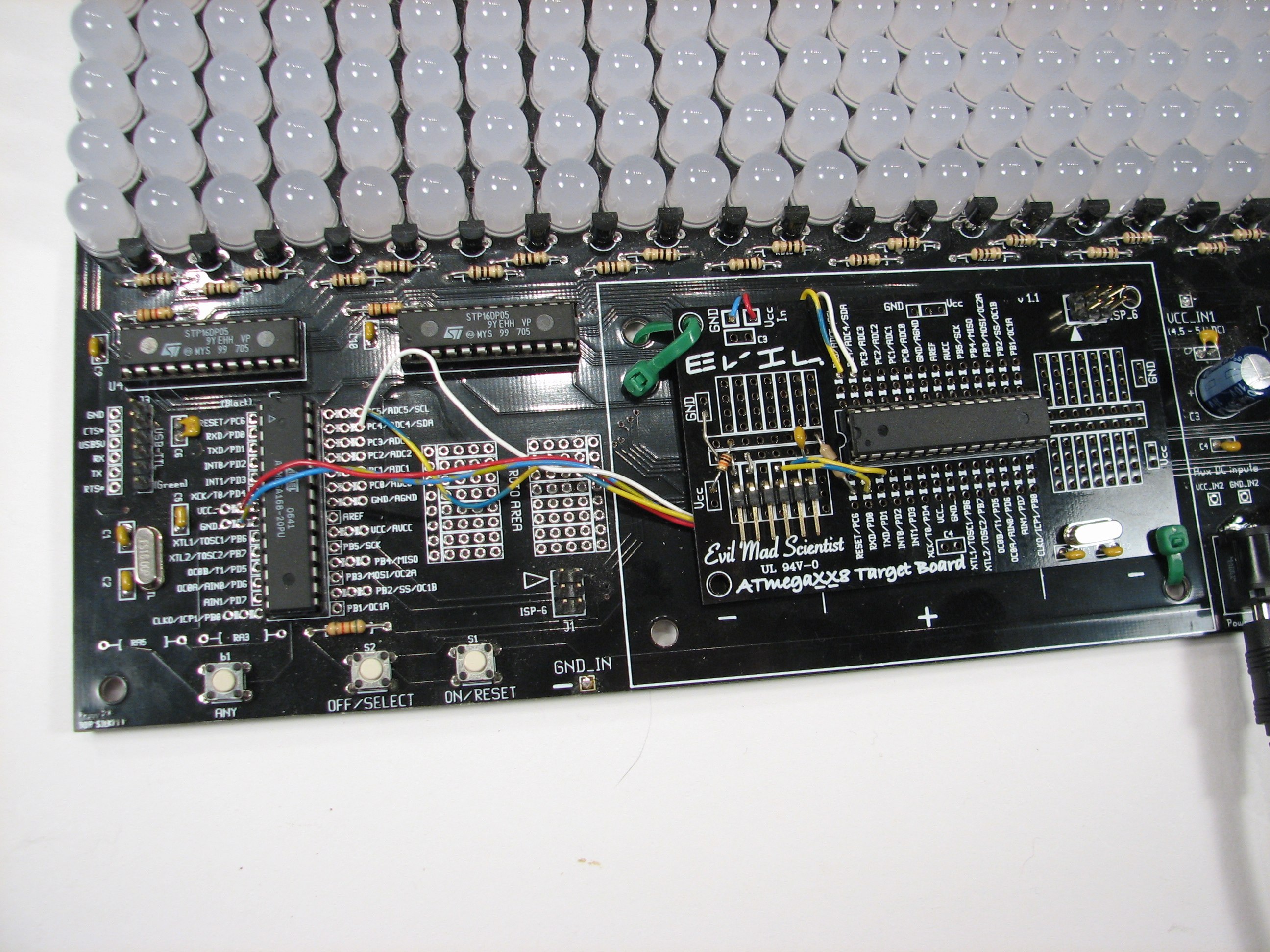
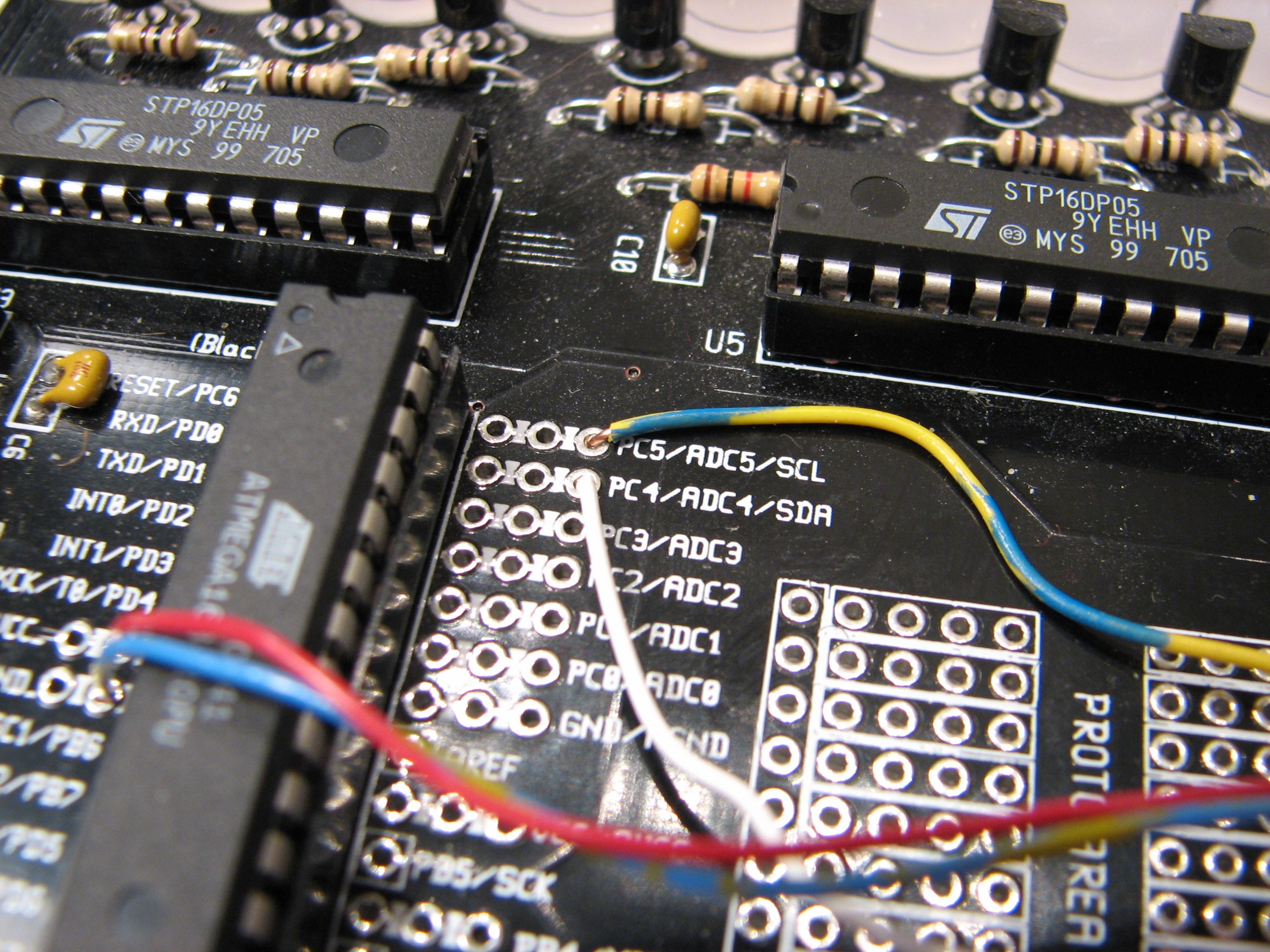
While Jay used a stock Arduino board in his demo, we just used a hacked “business card” breakout board, wired up where the battery box normally goes. The important part– no matter which version you are using is that the two TWI interface pins SDA (aka “Analog 4”) and SCL (aka “Analog 5”) are wired together between the Peggy and the Arduino. It’s straight-across wiring, so that pins SDA of both chips are wired together, and pins SCL of both chips are wired together. (The boards also have to share a common ground.)
For our parasitic version, we also powered the board from the Peggy 2, so that we wouldn’t need an additional power supply.
Since there are two microcontrollers, you’ll need one program for each. You can download the programs for both at the bottom of this page on Jay’s site. One program runs on the Peggy, and just waits for (or displays) incoming video data. The other program, for the intermediary Arduino, acts as a serial-TWI converter.
The host computer side software is written in Processing. You can download the Processing sketch here (4 kB .pde file).
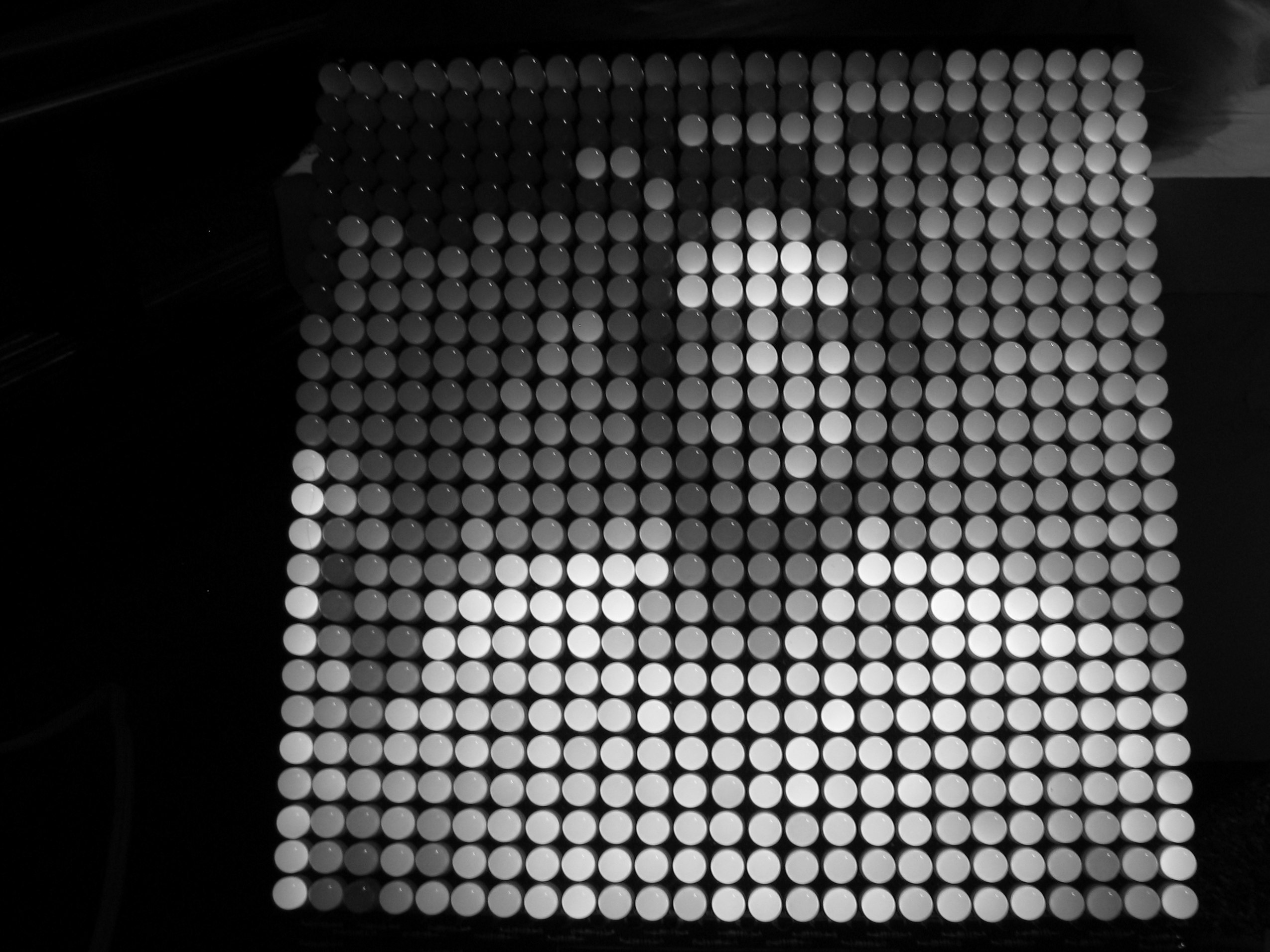
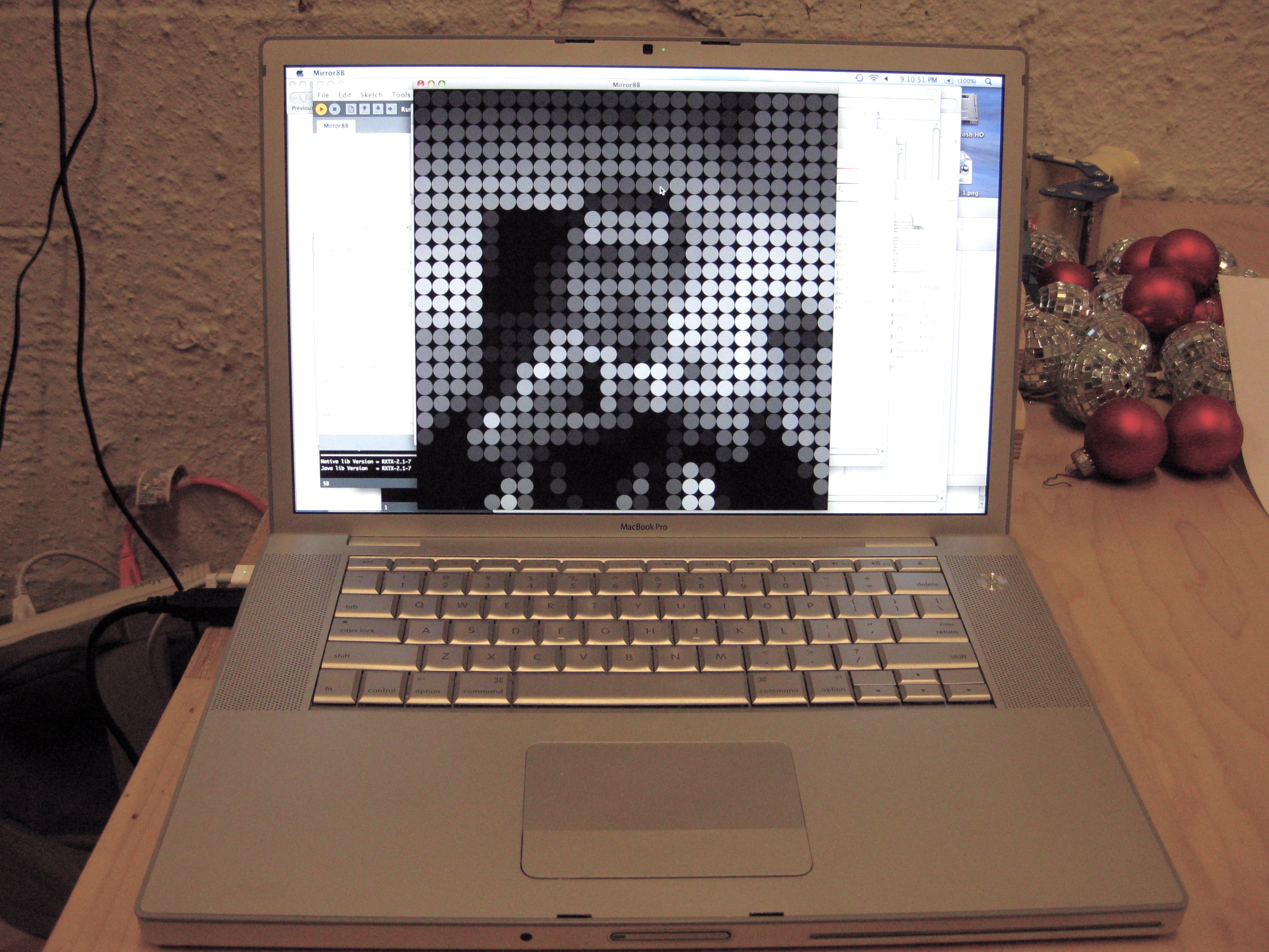
When it runs, it takes video input from a connected webcam (subject to the limitations of the Processing video capture library). The data is converted to grayscale, and drawn as a 25×25 grid of round dots, simulating the Peggy display. (This works without a Peggy as well, just in case you want to play with it.)
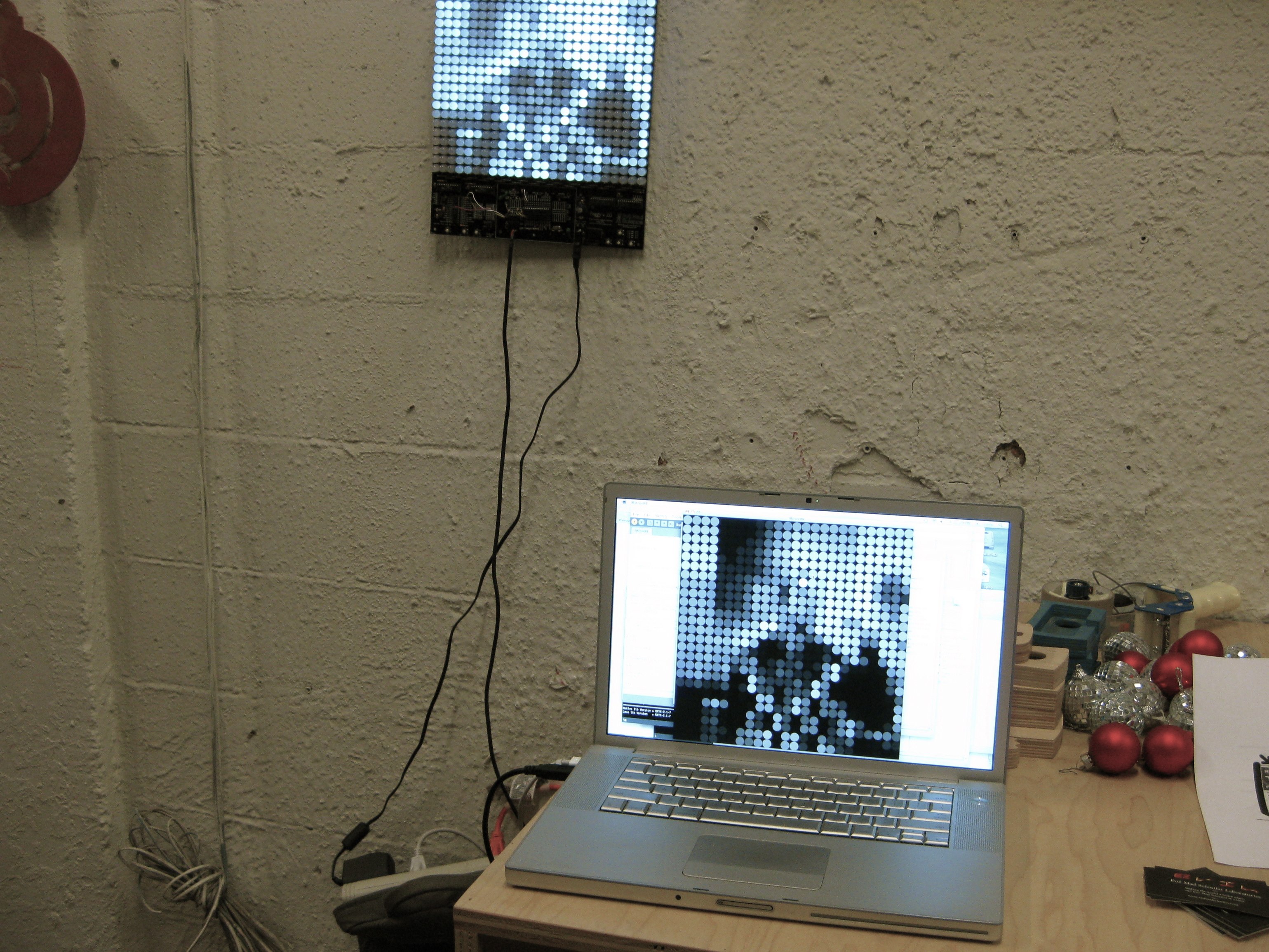
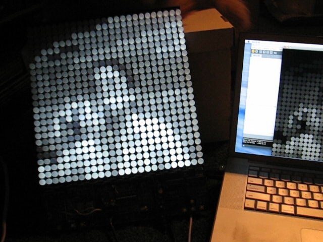
And, when hooked up correctly, the video shows up on the Peggy.
Embedded below is a short video (without narration) showing the VideoPeggy in action. If you can’t see it here, click through to flickr for the video. Performance seems to be good at about 15-17 frames per second with 16 levels of grey.
Update: We’ve uploaded a version of the TWI-receive software for the Peggy 2, formatted as an Arduino sketch and verified to work on both the ATmega168 and ATmega328P. You can download it here.

Is the link on this page to the MirrorPeggy.pde correct? It does not create a 25×25 grid for me. It creates a row of 4 small video images with varying amounts of blur.
I’ve just verified that it works okay on another computer– Anyone else have a report?
—
Windell H. Oskay
drwho(at)evilmadscientist.com
http://www.evilmadscientist.com/
The code seems to run fine for me, I just don’t get a 25×25 display. I get 4 small video windows in a row…each about 1.5 inches square that display the video from my isight camera. The two windows in the center are somewhat blurry. I’m not sure how this could possibly run so much differently using the same code???
Never mind…of course it was my mistake. Too many Processing windows open.
Great project. Just a note on the color reduction to 16 grey levels.
If you add a tiny random element into the color, specifically +/- half a grey level (in your case +/-8 if you’re converting from 256 to 16 levels) and then downsampling the color you’ll lose the banding effect (called Mach Banding) and get a smoother better result.
You don’t have to use random noise, you can also use a regular grid of constant offsets called an "Ordered dithering" mask, but the random idea works best for temporal data (stuff that changes over time) as the human visual system is very forgiving of randomness.
I have given up trying to get this to work with windows and my webcam, gonna try and find a macbook on ebay, what spec machine are you using here to get those framerates?
thanks.
If you are having trouble getting this to work "at all," the problem probably isn’t one of frame rate– you may have a bad connection, or perhaps the wrong program installed on one of the chips. You can also try adjusting the frame rate manually. In the processing program, search for "frames per second" — which is by default set to 15, I think. Try changing that to 1 or 5, and see if that makes any difference.
—
Windell H. Oskay
drwho(at)evilmadscientist.com
http://www.evilmadscientist.com/
Im not that far yet, havn’t even ordered the peggy. Im just having an intial play with with processing to make sure this is the right solution for my project. It seems that there are far two many problems trying to use it in a windows environment, problems with video capture, quicktime and java… Its about time I got hold of a used mac, so really just wondering what spec is needed to get that kind of frame rate?
thanks
We were able to get decent performance on just about any recent-vintage mac, even a slow-as-a-slug macbook air. Maybe 1.5 GHz Intel Core Duo would be a good spec to aim for.
—
Windell H. Oskay
drwho(at)evilmadscientist.com
http://www.evilmadscientist.com/
How would I go about flipping the video horizontally, cant find anything in the settings so think it needs to be done in the code? but have no idea…
Im using a source from a usb capture.
thanks.
You could do this at any stage: on the computer, in the translation to I2C or on the Peggy– all depends where you’re most comfortable programming.
—
Windell H. Oskay
drwho(at)evilmadscientist.com
http://www.evilmadscientist.com/
…comfortable programming – no where really!
I’m assuming I need to change this in processing:
int loc = (video.width – x) + y*video.width; // Reversing x to mirror the image
however nothing seems to happen when I change it, any advice?
thanks.
As I said, you don’t *need* to do it in processing– it can be done at any stage in the pipeline.
But, if you want to do it in processing, replace this line:
loc = (video.width – xs – 1) + ys*video.width;
with this:
loc = xs + ys*video.width;
—
Windell H. Oskay
drwho(at)evilmadscientist.com
http://www.evilmadscientist.com/
And what would that line be if I need to flip it vertically?
Thanks so much for the help!
Ok, so I happened to realize that I can just flip the camera upside down for this application, so don’t worry about that unless you want the challenge.
Is it possible to get a copy of the peggy firmware as an arduino sketch? as I’m having difficulties porting it using the instructions provided, and only have the usb-ttl ftdi cable.
Yes, we’ve just posted a link to it at the bottom of the article.
—
Windell H. Oskay
drwho(at)evilmadscientist.com
http://www.evilmadscientist.com/
Very cool. Could this be used in conjunction with a POV display for more pixels?
That would really up the coolness factor..
how big is it possible to make this, and what is the cost per sq m?
Great project. I seem to have it almost working except the connection between processing and the arduino isn’t quite right. It’s only refreshing every two seconds or so (inconsistently) and the image seems to be offset by a number of pixels.
Running Jay’s test pattern script on the arduino works great.
Any suggestions?
I think that someone reported a similar problem in the forums; check there. And if you need more help, ask for it there, not in the blog comments, please. ;)
Windell H. Oskay
drwho(at)evilmadscientist.com
http://www.evilmadscientist.com/
Could this work with the Video Experimenter shield – so no computer?
So far as I can see, the Video Experimenter shield does require a computer, and I’m not sure how you would interface that to a Peggy in any case.
Windell H. Oskay
drwho(at)evilmadscientist.com
http://www.evilmadscientist.com/
great project –
i played with the code in order to change the resolution
-in order to have more than 25 x 25 cells
and probably combine more than just 1 peggy-
… but didn’t succeed yet;
may i ask for any advice on how to proceed
to get more than a 25z25 resolution?
The tricky thing is how to network the Peggy kits. One way is to use I2C, another is to use a multipoint serial like RS485. Here’s one working example: http://hackaday.com/2009/12/19/peggy2-x2-with-video/
Windell H. Oskay
drwho(at)evilmadscientist.com
http://www.evilmadscientist.com/
What are the connections all going to on the atmega target board? Also to program should i use the isp_6 connection or FTDIfriend. One more question is how to wire or add the usb cord to the target board to receive video. Please email me ryboyd323@gmail.com
This is really not a good place for back-and-forth discussion. Please use our forums or contact us directly for tech support on questions like these.
Also, this whole method is somewhat out-of-date. On current-generation Peggy2 and Peggy 2LE boards, you *do not* need to use this method– just configure it for “SER” mode (as opposed to “P2” mode) and connect the Peggy directly to your computer through the FTDI cable, and stream video that way, using our sample code.
Windell H. Oskay
drwho(at)evilmadscientist.com
http://www.evilmadscientist.com/