


Here’s an neat idea for a jack-o’-lantern: Hide a single white LED just beneath the thin surface of the pumpkin. And program it with the same slow “breathing” effect that indicates sleep on Mac computers.
The result? A pumpkin that sleeps like a Mac. It’s actually quite striking, in part because the effect becomes invisible every few seconds. It’s also an easy microcontroller project: our demonstration video and build instructions follow.
Here’s a quick walkthrough of the project, hosted at youtube:

This project is based on an ATtiny2313 microcontroller. The other essential components are an LED, resistor, and power source; we suggest using 3xAAA holder with switch, but a 3xAA holder will work just as fine. You’ll also need some way of programming your chip. We use the Adafruit usbtinyisp programmer hooked up to the chip with a minimal target boardconfiguration. The only essential part that you need for the target board is the six-pin header (shown above) that hooks up to the programmer.

Here are two examples of target boards for the ‘2313– the minimal one from the target board article, as well as our custom built ‘2313 target board. We’ll be using this one from here on out, just for ease of wiring.

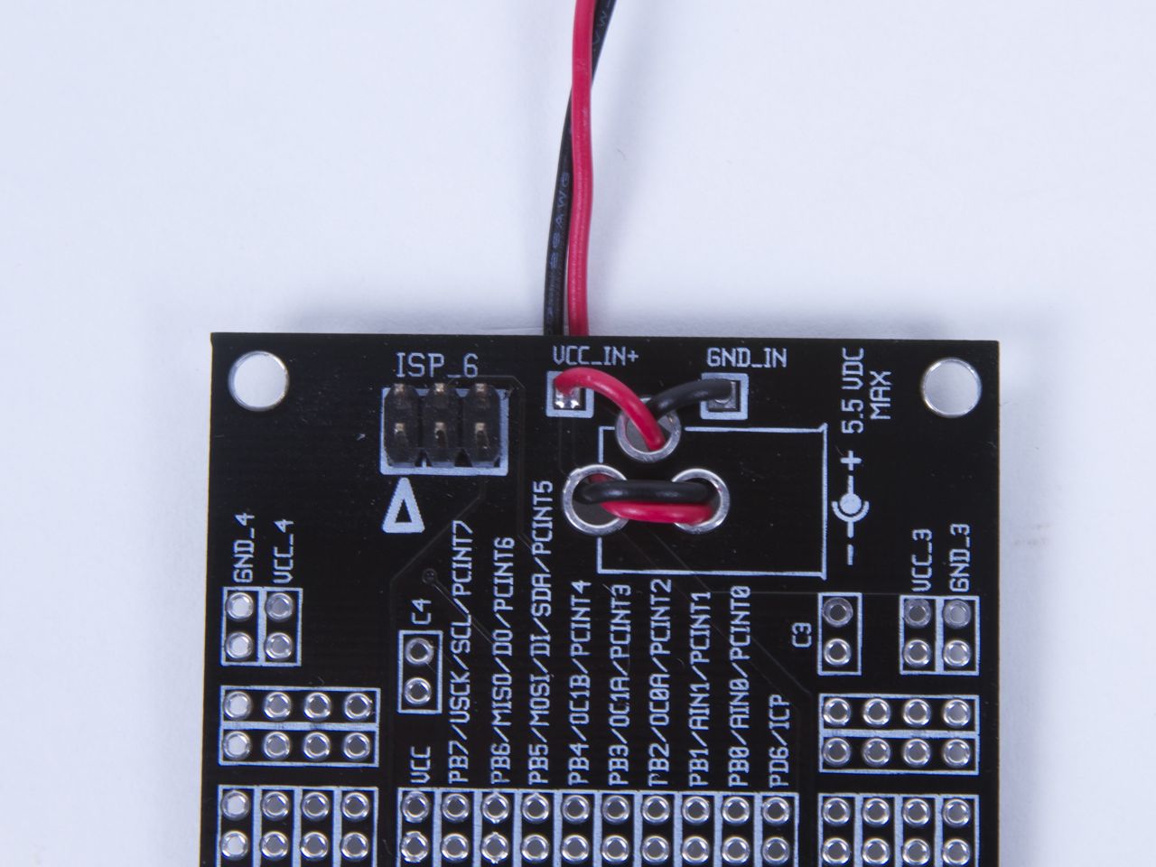
First step is to wire up the target board with the chip, 6-pin ISP header, and powerA neat trick is to wrap the wires through existing but unused holes on the board for strain relief.
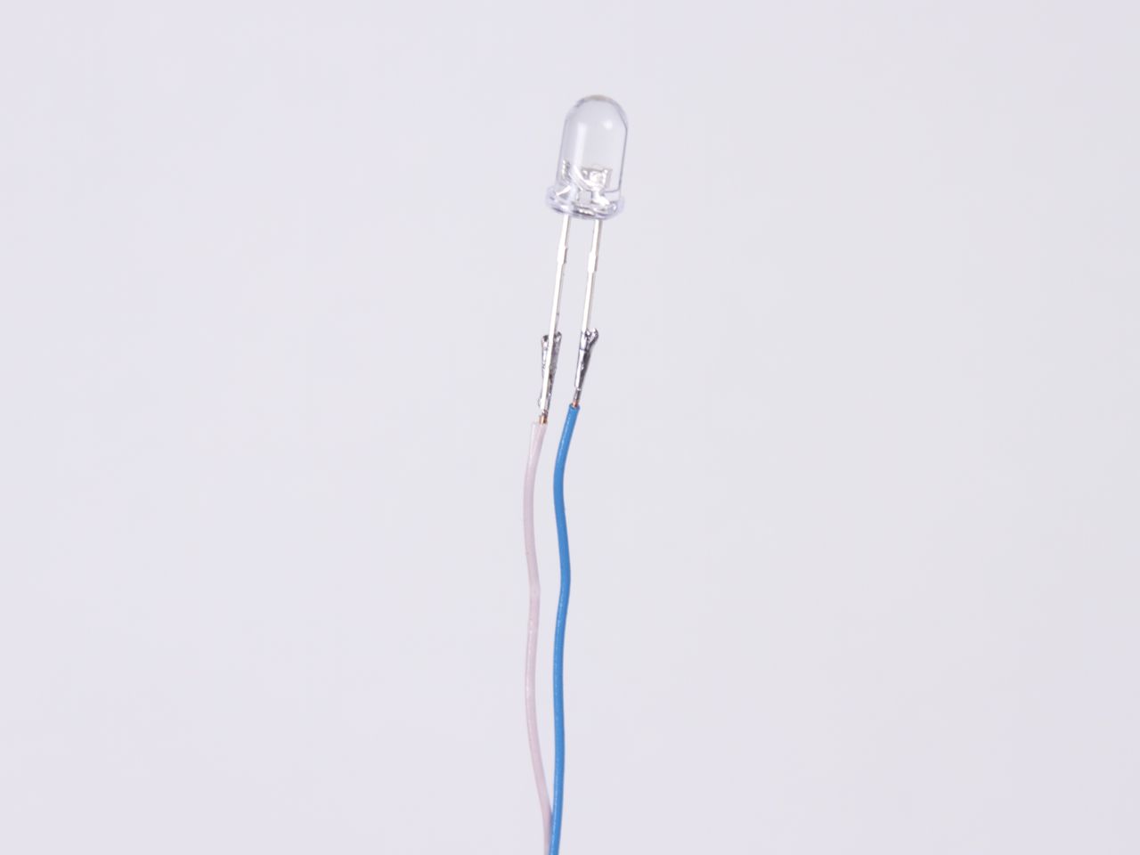
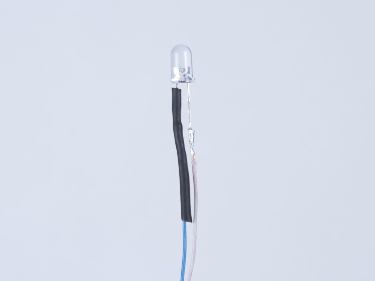


We are using an ultrabright 5 mm white LED with a clear lens. We hooked it up to the target board through some long insulated wires so that it can be arbitrarily positioned within the pumpkin. We also used a layer of black heat shrink tubing to make sure that the leads don’t touch and an overall wrapper of clear heat shrink tubing. The pumpkin is a moist environment, and it can help to keep the moisture off of the electronics.

Here’s a close-up of the connections on the board. The output signal comes out of OC1A, goes through the resistor, to the LED, and from there to ground. For a white LED and 4.5 V power (3xAAA), about 20 ohms is appropriate for the resistor.
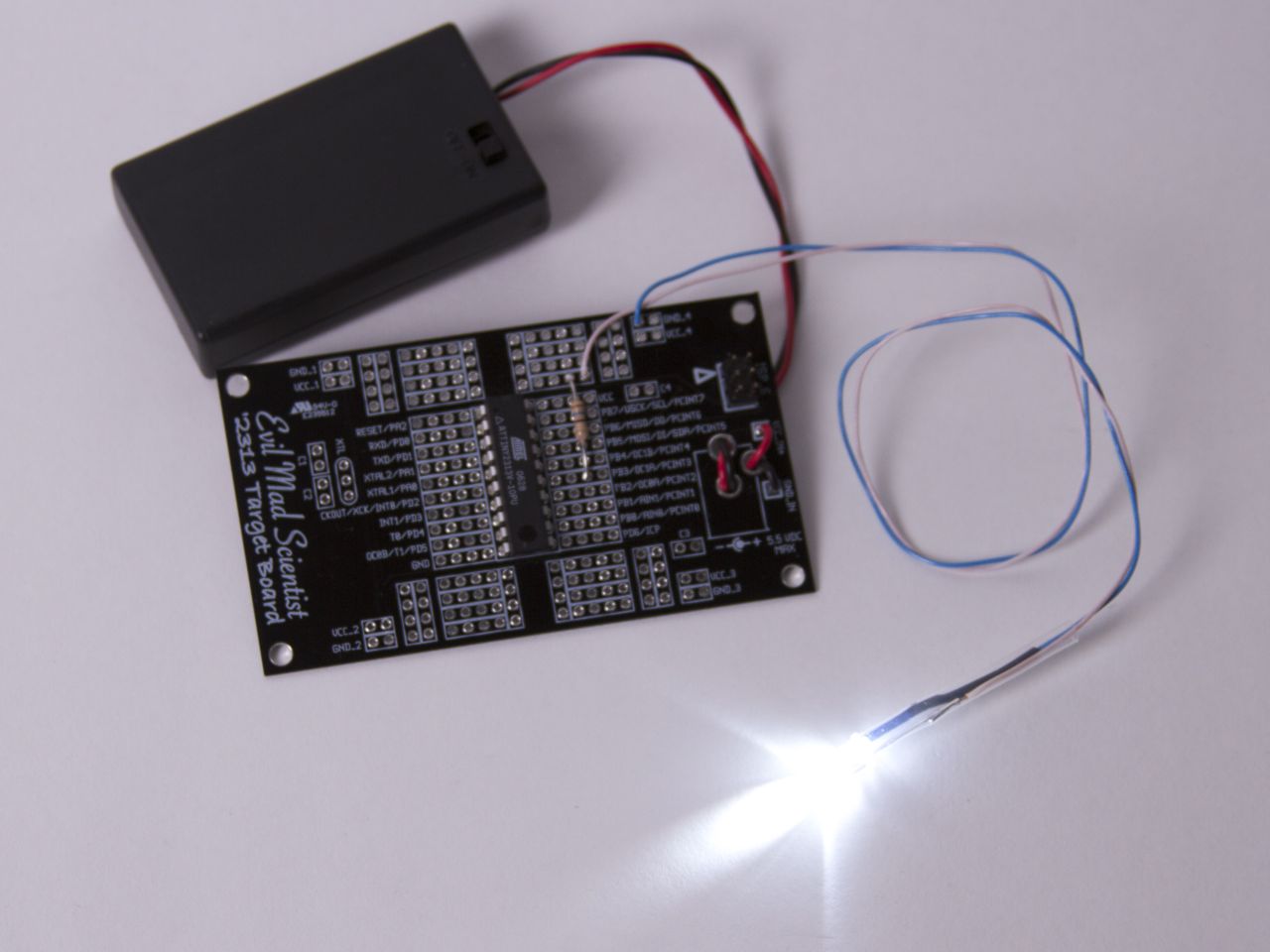
That’s actually all the electronics hardware that there is– the rest is programming and pumpkin carving.
The source code for this project– and you’ll need to program the chip before it lights up the LED — is available for download
here (12 kB .zip archive) It’s an avr-gcc source file. (If you’re new to AVR programming, you might want to start by looking at our list of resources for getting started with AVR microcontrollers.) We got some hints for how to get the feel right by looking at this old project from Adafruit.


Next, the victim pumpkin.
We found a nice face on our pumpkin, where we could locate the LED. On the opposite side, we cut an opening that would not be visible from the front– going for that “no visible seams” look, right?
Then we scooped out the contents of the pumpkin, washed and dried the inside, and thinned the front wall. We used a 3/16″ (4.75 mm) drill to make an incision that would hold the LED dead center in the front. This is the tricky part– you need to twist the drill so that it almost pokes through.
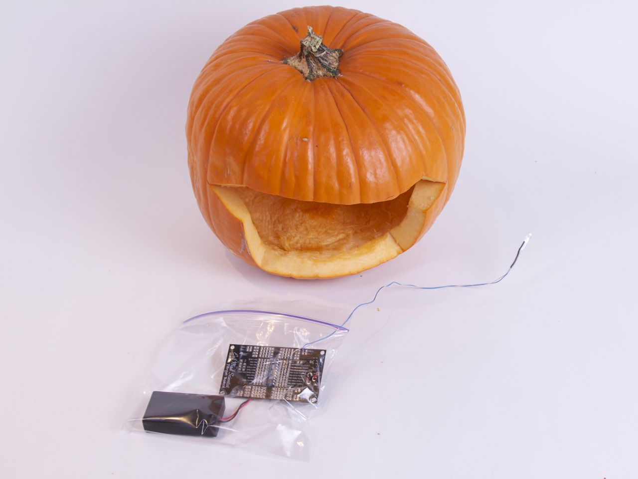
Put the electronics– except the LED –in a plastic bag, sealed to the extent practical.
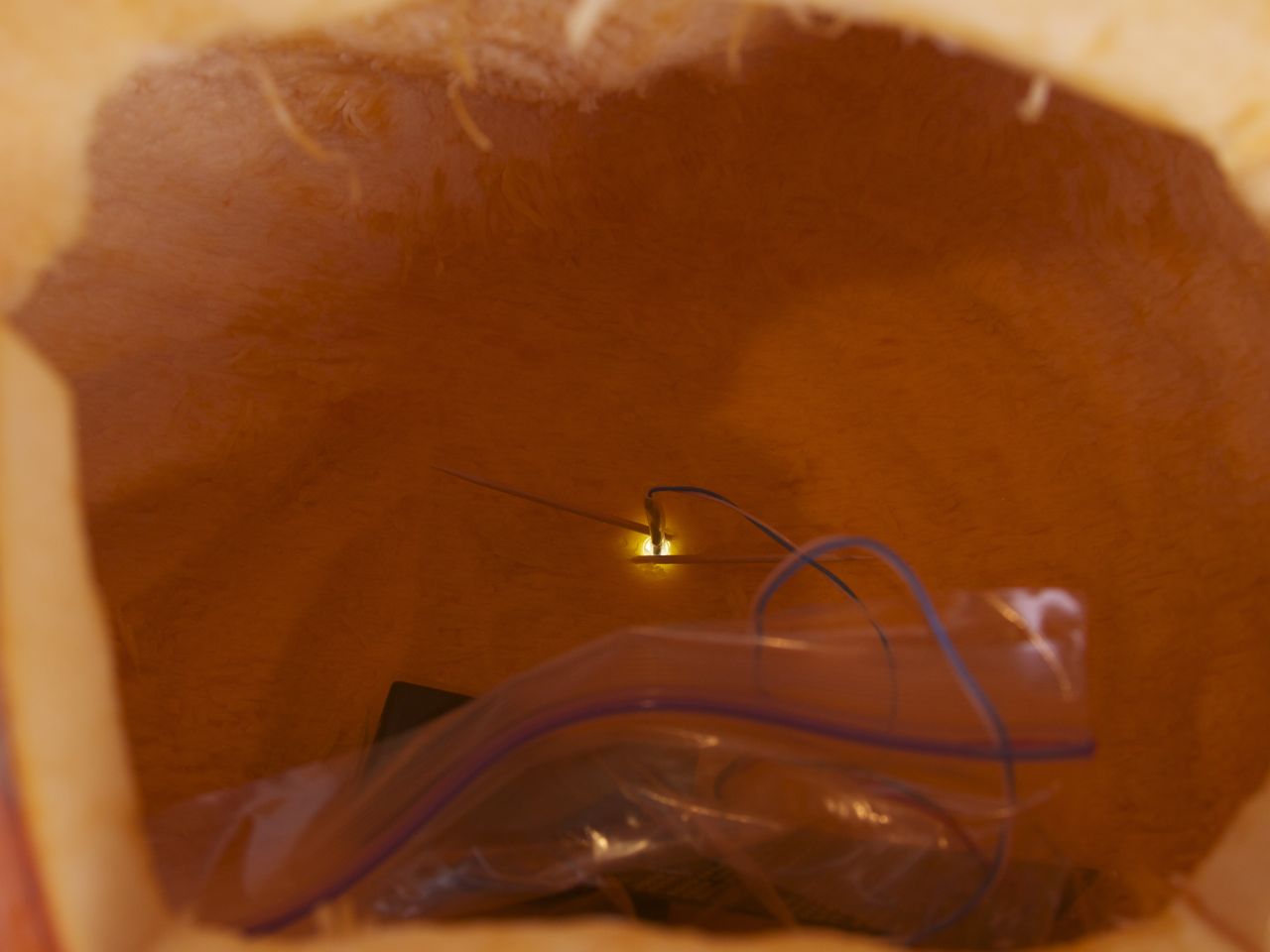
Stick the LED in its hole, and (optionally) wedge it in place with a couple of toothpicks.

And that’s all there is to it. But beware: the LED effect is convincing. You might have to keep explaining, “No, I didn’t hide a Mac Mini in there.”
You can find more pumpkin projects in our Halloween Project Archive.
Make another one, but this time strip just the very front layer of the pumpkin in the shape of the Apple, er, Apple.
Or perhaps the IEC 5009 sleep symbol?
Can’t a similar effect be achieved with a 555 in astable mode ?
It was my understanding that the frequency and duty cycle of astable mode are fixed and determined by the resistor values when in astable mode.
How would one create a sinusoidal increase and decrease in the PWM frequency in astable mode with a 555?
Not a 555, but dual op-amp… http://www.discovercircuits.com/H-Corner/ho-train-lite.htm
I haven’t seen it running, so it may not mimic the Mac as well.
http://www.instructables.com/id/ThrobbingFading-LED-with-555-Timer/
470 ohm resistor (or a resistor to drop the current for your desired led from around 8 volts.)
33k resistor ( or a 100k potentiometer for adjustable fade times)
LED ( I used Blue)
100uf Capacitor
555 Timer
Generic NPN Transistor
Excellent suggestion. That schematic worked like a charm.
http://www.youtube.com/watch?v=V0T_dSrLm9o
i want to see one with the knight rider led array ^^
http://www.evilmadscientist.com/article.php/larsonkit
Neat, but I think you need to add a second LED. Eyes would look spookier.
Aye – we now have an evil George Bush with two eyes.
Used and ATMega8 – only about three lines to change.