


Simple Solar Circuits:
How to get started adding solar power to your small electronics projects. Use the sun to power small solar and battery powered night lights, garden lights, and decorations for halloween.
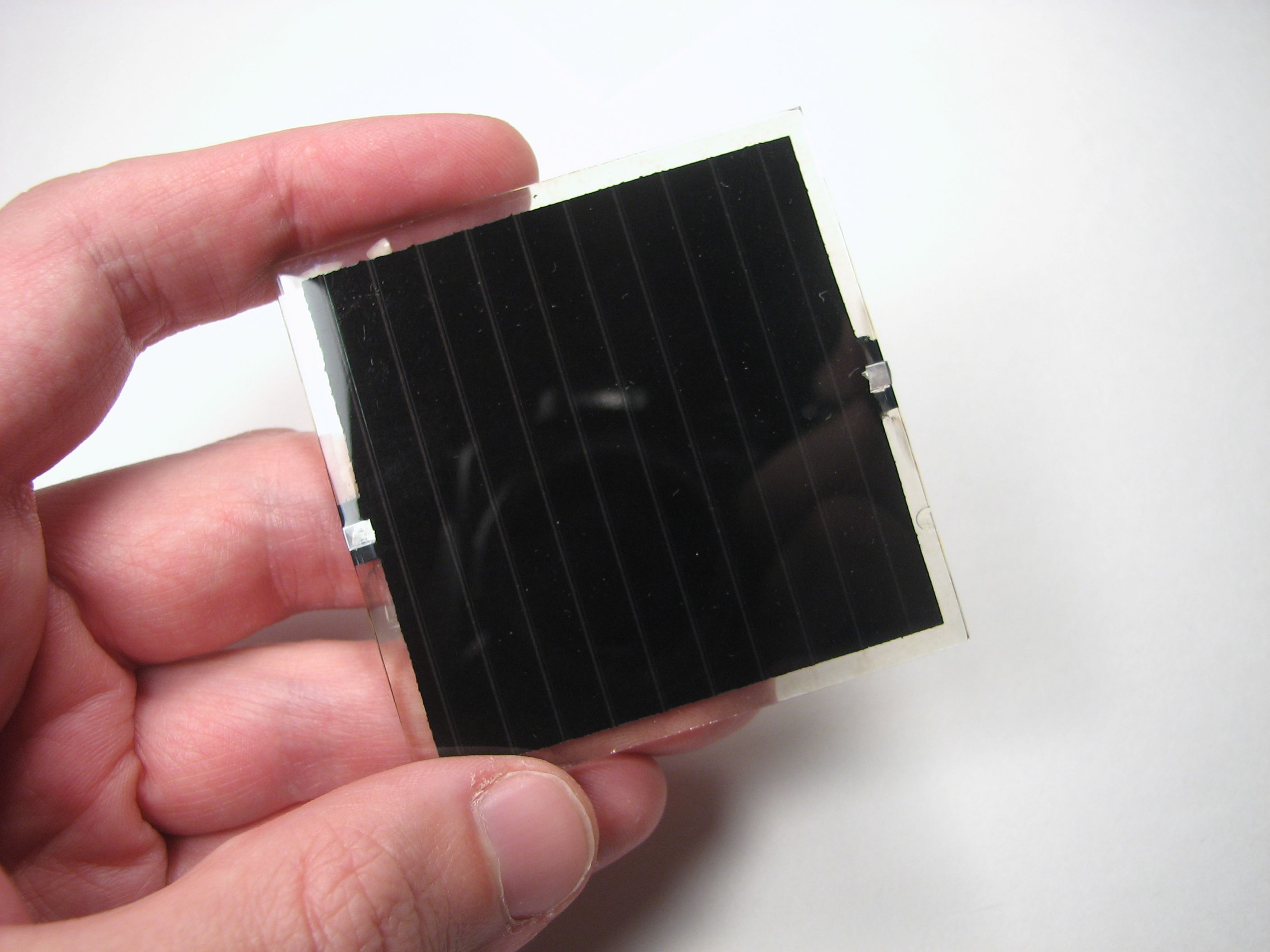
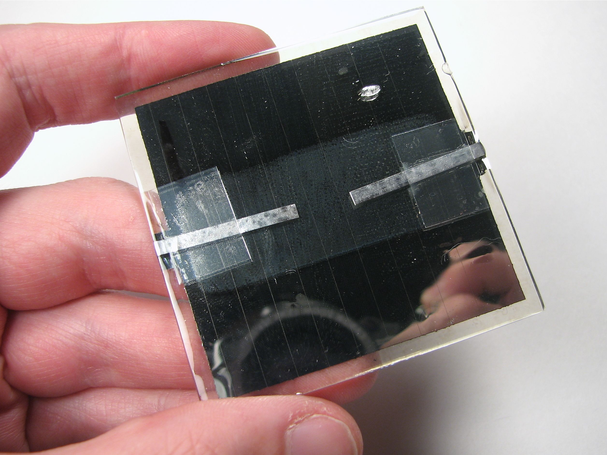
The first part of a solar circuit is… a device for collecting sunlight. To keep things simple, we’re using a single nicely made small solar panel for all of these circuits. The panel that we’re using for these circuits is this one, part number PWR1241 from BG Micro, about $3 each. This is a monolithic copper indium diselenide solar panel, apparently printed on a 60mm square of glass and epoxy coated for toughness. On the back of the panel are two (thin) solderable terminals, with marked polarity. (While you can solder directly to the terminals, be sure to stress-relieve the connections, e.g., with a blob of epoxy over your wires.) In full sunlight the panel is specified to produce 4.5 V at up to 90 mA, although 50 mA seems like a more typical figure.
[Before we move onto our first examples, a word of caution: These are small simple circuits. In building these, we will quite intentionally gloss over a number of minor details and issues that are unimportant at these low powers, but could become critical if you were to try to scale up.]
Direct Drive:
The most obvious way to use power from a solar panel is to connect your load directly to the output leads of the solar panel.
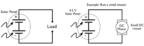
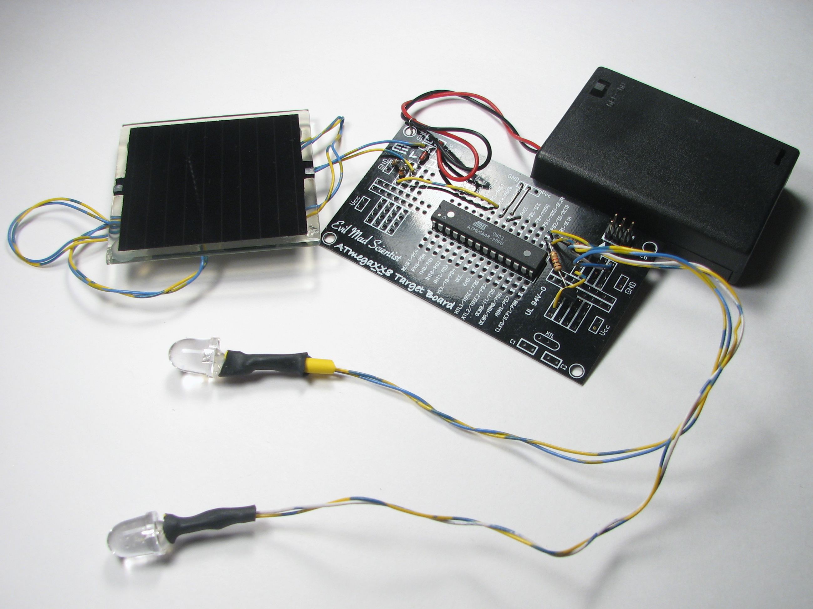
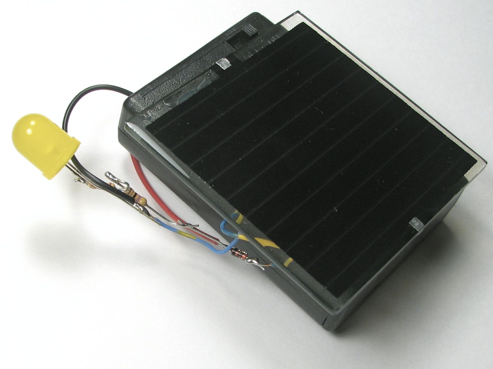
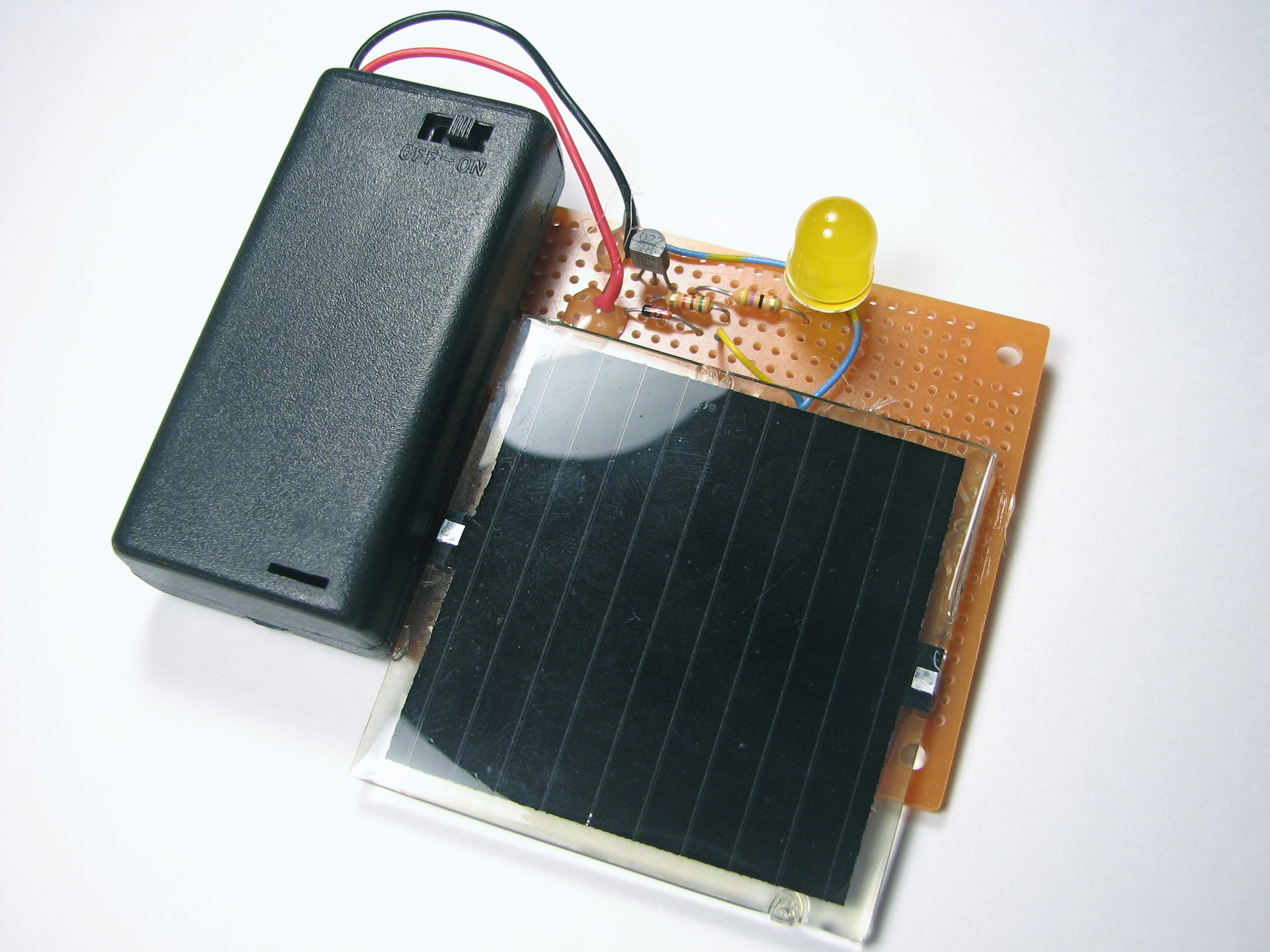
Here are a couple of examples of this in practice:
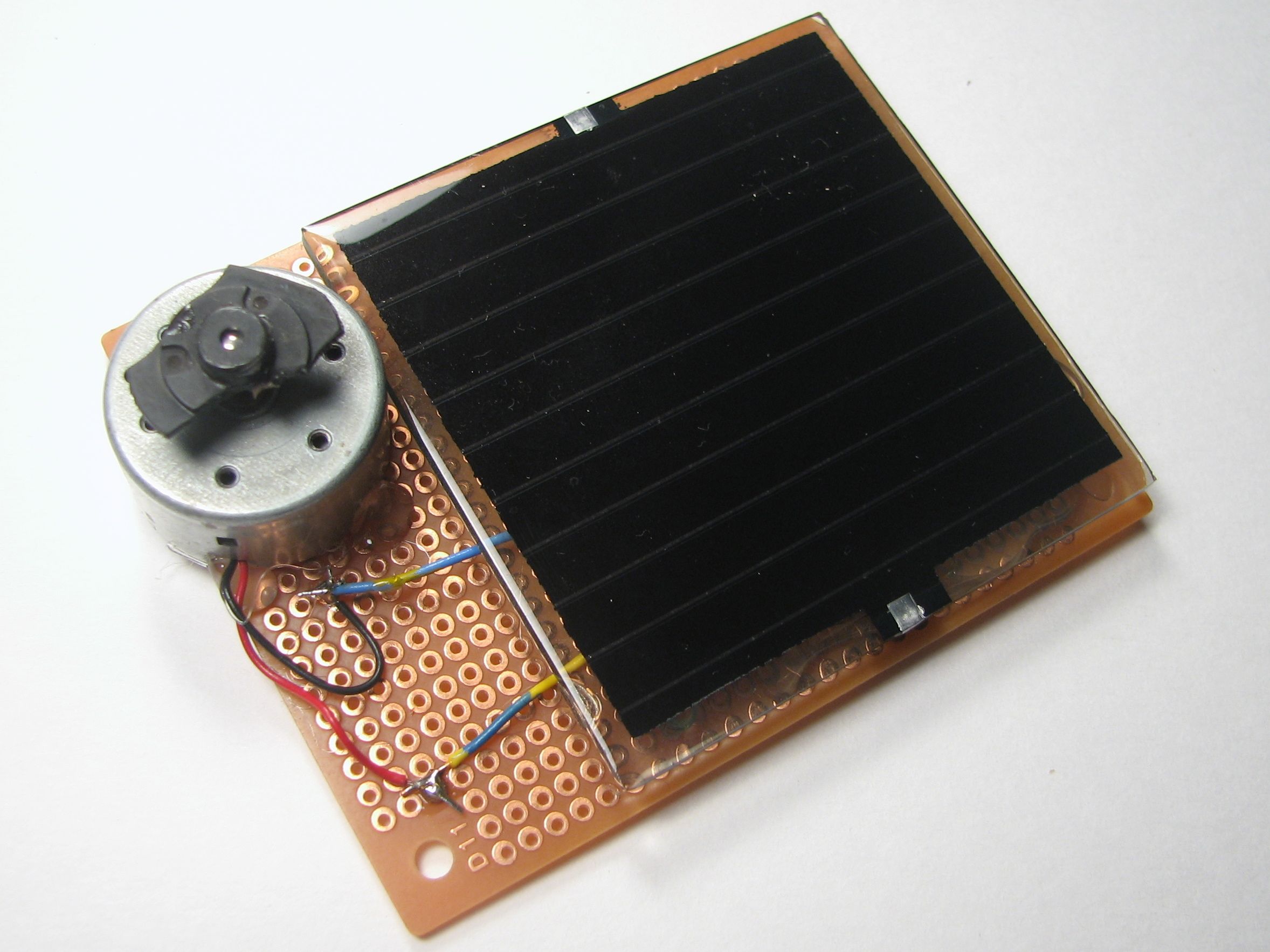
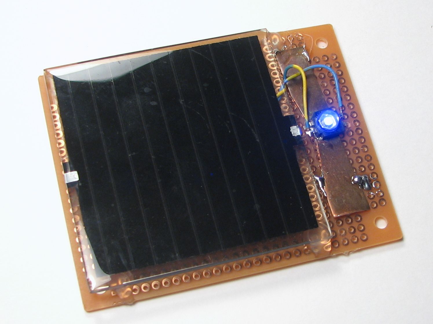
On the left, we’ve hooked up one of our little solar panels directly to a small motor taken from an old CD player. When you set it out in the sunlight or bring it close to a lamp, the motor starts to spin. On the right we’ve hooked one of the panels right up to a high-power blue LED. The reason that we’ve used a high-power LED here is that it can easily withstand 50-90 mA from the solar panel– a “regular” LED designed for 20 mA would be destroyed by that current. (The LED is the same type that we used for our high-power LED blinking circuit.)
Interruption-resistant direct drive:
The “direct drive” circuits work well for their design function, but are rather basic. They provide no energy storage, and so are quite vulnerable to blinking out when a bird or cloud passes overhead. For some applications, like running a small fan or pump, that may be perfectly acceptable. For other cases, like powering a microcontroller or other computer, a brief power interruption can be disruptive. Our next circuit design adds a supercapacitor as a “flywheel” to provide continued power during brief interruptions.
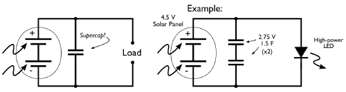
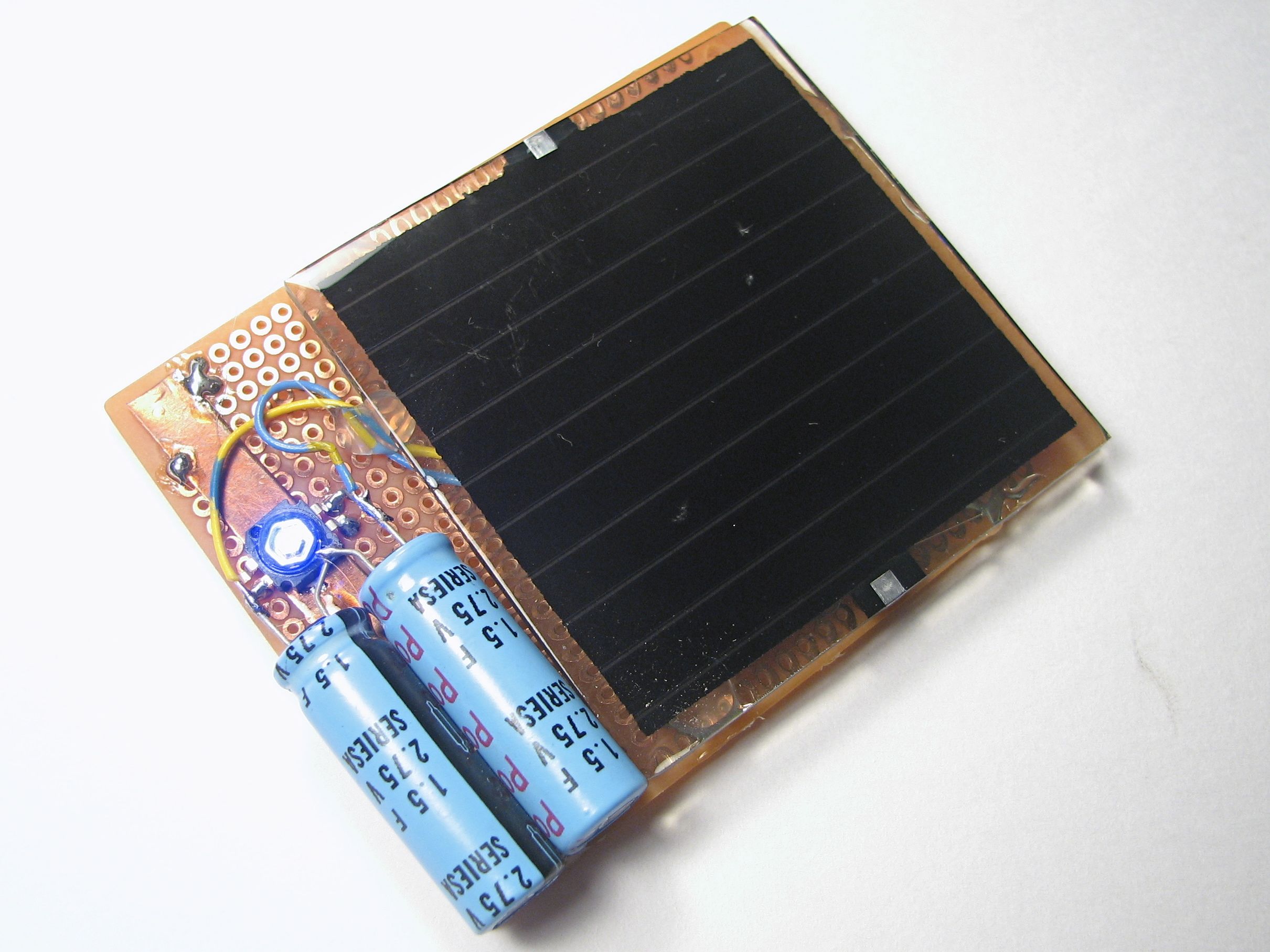
Instead of adding a single supercapacitor, you might notice that we’ve actually added two. That’s because the supercaps that we had on hand are rated for 2.75 V– not enough to handle the 4.5 V output of the panel when sunlight is present. To get around this limitation, we used two of the caps in series, for which the voltage ratings add, giving us a barely-okay total rating of 5.5 V. (Note: be careful adding capacitors of different values in series– the voltage ratings may scale in non-obvious ways.) When first exposed to the light, this circuit takes about 30 s to 1 minute to charge the capacitors enough that the LED can turn on. After it’s fully charged, the circuit can be removed from the sunlight and still drive the blue LED for about 30 s to 1 minute– a very effective flywheel for light duty applications.
Adding a battery
While interruption resistance is nice, a capacitor generally does not provide sufficient energy storage to power a solar circuit for extended periods of time in the dark. A rechargeable battery can of course provide that function, and also provides a fairly consistent output voltage that a capacitor cannot. In this next circuit, we use the solar panel to charge up a NiMH rechargeable battery and also LED off of the power, which will stay on when it gets dark out.
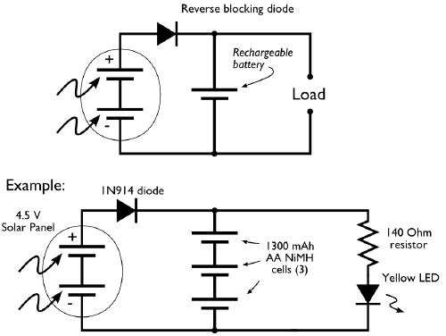
In this circuit the solar panel charges up a 3-cell NiMH battery (3.6 V). Between the two is a “reverse blocking” diode. This one-way valve allows current to flow from the solar panel to the battery, but does not allow current to flow backwards out of the battery through the solar panel. That’s actually an important concern because small solar panels like these can leak up to 50 mA in the reverse direction in the dark. We’re using a garden-variety 1N914 diode for reverse blocking, but there are also higher-performance diodes available that have a lower “forward voltage.”
In this design we are continuously “trickle charging” up the battery when sunlight is present. For NiMH batteries and sealed lead-acid batteries (the two types that are most suitable for this sort of un-monitored circuit) it is generally safe to “trickle” charge them by feeding them current at a rate below something called “C/10”. For our 1300 mAh battery cells, C/10 is 130 mA, so we should keep our charging below 130 mA; not a problem since our solar panels only source up to 90 mA.
The other thing to notice about this circuit is that it’s pretty darned inefficient. The LED is on all the time, whenever the battery is at least slightly charged up. That means that even while the circuit is in bright sunlight it is wasting energy by running the LED: a sizable portion of the solar panel current goes to driving the LED, not to charging the battery.
Detecting Darkness
We have written recently about how to make a useful dark-detecting LED driver circuit. That circuit used an infrared phototransistor. To add a darkness detecting capability to our solar circuit is even easier, actually, because our solar panel can directly serve as a sensor to tell when it’s dark outside.

To perform the switching, we use a PNP transistor that is controlled by the voltage output from the solar panel. When it’s sunny, the output of the panel is high, which turns off the transistor, but when it gets dark, the transistor lets current flow to our yellow LED. This circuit works very well and is a joy to use– it would make a good upgrade to the dark detecting pumpkin to make it go solar with this circuit.
A solar garden light circuit
While the last circuit works well for driving a yellow or red LED, it runs at 2.4 V (the output of the NiMH battery), it does not have sufficient voltage to drive a blue or white output LED. So, we can add to that circuit the simple Joule Thief voltage booster to get a good design for a solar garden light: A solar-charged battery with a dark detector that drives a Joule Thief to run a white output LED.
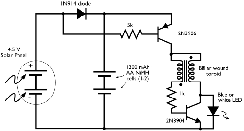
Naturally, you’d want to give this a tough, weatherproof enclosure if it were going to be run outside. (A mason jar comes to mind!) This circuit is actually very close to how many solar garden lights work, although there are many different circuits that they use.
Adding a microcontroller
Our last circuit examples extend the previous designs by adding a small AVR microcontroller. We use the voltage output from the solar panel again to perform darkness detection, but instead take it to an analog input of the microcontroller. The microcontroller is potentially a very low current, efficient device that lets you save power by not running the LED all the time, but (for example) waiting until an hour or two after darkness and/or fading the LEDs on or off, or even intermittently blinking for very low average power consumption.
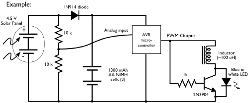
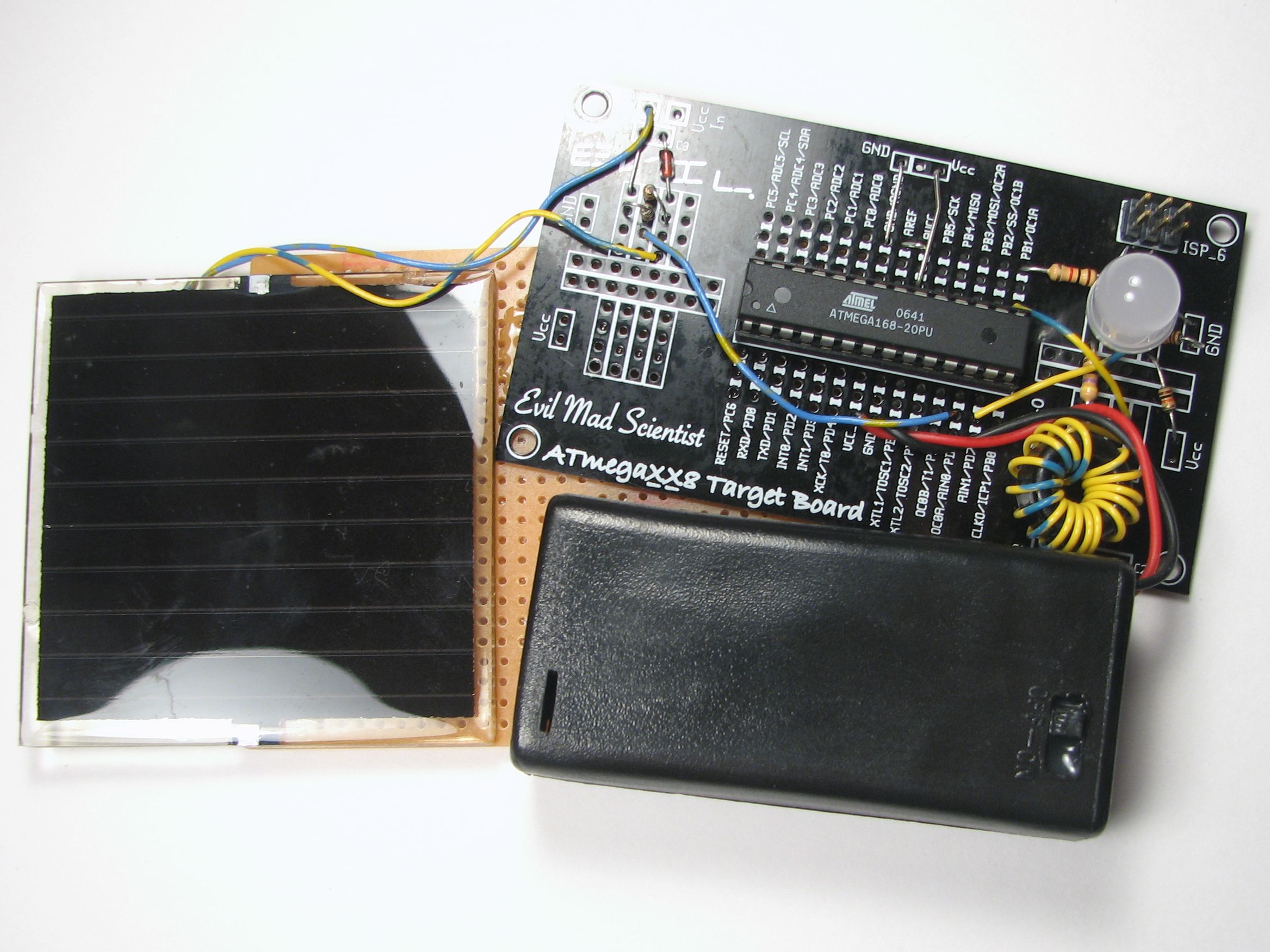
In this example we have the PWM (pulse-width modulation) output of the microcontroller driving a Joule Thief style voltage booster to run the white LED. (This is one of many, many different working designs for this sort of boosting circuits.)
We also made a second version of this circuit, with two red LED outputs to make a spooky Jack-o’-lantern:


To finish it up, we carved a beautiful white pumpkin and added this circuit to make our microcontroller-driven, dark-detecting, solar-powered programmable pumpkin, which faded its eyes in and out one at a time. Note the long leads on the solar panel and wires to the LEDs to reach.
We hope that you might find this introduction to simple solar circuits helpful; let’s see those solar jack-o-lanterns!
You can find more pumpkin projects in our Halloween Project Archive.

I’m having a problem figuring out how to rig one of these up to charge 4AA’s that are connected to 8 Amber LED’s and have a dusk to dawn circuit. I have 2 panels that are 4.5 volts +/-, 8 – 3.2 volt-20ma Amber LED’s, but no charging circuit. I think it’s best in the long run to have a full charging circuit for this project. Do you think I am correct? I also don’t have a properly configured dusk to dawn circuit. Any idea’s? Any help would be great. Thanks.
Hello,
I have a question about "A solar garden light circuit".
My solar panel generates 7V , 1.4 watt. I have two Ni-MH batteries, and I want to power 3 (not 1) white LED’s. What should I change in that circuit?
ps. I am talking about circuit without micro-controller.
Appreciate Your help.
Best regards,
Lucas
I have been looking for a very long time now to make somehthing similar, but with a smal fan attached. What I want to make is a ventilator that blows day and night. It will be one that either consumes 2V/40 mA or a larger one that consumes 3,5-4V and 90 mA. It would be okey if it turns on and of lsome of those gardenlamps at night in order to use less energy from the batteries.
So the fan needs to run 24h (it is for a thermometer screen).
Thanks in advance!!
Hi, thanks for the awesome resourceful article. Maybe you can help me… I’m wanting to create a set of solar panels that will directly charge a cell phone (not panels to battery to cell phone). I’ve bought 10 1v 200ma panels and wired them in series and parallel to produce what I thought would be 5v @ 400ma. I also used a diode from the panels but nothing else. However, when I connect them to my cell phones via female usb (both a Galaxy Nexus and Iphone 4s), the phones indicate that they’re charging but don’t charge. The phones both eventually lost power. On my Nexus, I have a current app that tells me it’s discharging at -100ma while the battery icon shows that it’s charging. I also turned the phones completely off and tried to charge, but they both still indicate charging but actually lose charge when powered back on.
The short circuit current of my panels setup is showing up to 300ma. With a multimeter hooked up while under load of my phone with mid-day sun in Texas, the meter shows that the current is rapidly changing in the 20-40ma range, which is nothing close to the 400 I was hoping for. Why would this be? Could the phone be losing charge because the panels aren’t putting out enough or a steady enough current? I’m sure my diode is in the correct position so I still don’t understand why they’re losing power. Do I need a capacitor to steady the current out?
Thanks a lot.
Cell phones usually need a fairly precise power source. You might consider adding an intermediate battery or voltage regulator, to make sure that you can provide a steady 5 V, or whatever your phones actually require.
Windell H. Oskay
drwho(at)evilmadscientist.com
http://www.evilmadscientist.com/
Is there any chance of you posting the code used in your final circuit? While I’ve written a few small blinken lights programs, I don’t have any experience using the ADC, PWM outputs, or interrupts. At best I’ve just manually altered duty cycles on regular outputs to fade LEDs. Examples of this in action would be excellent.
Thanks.
Hello,
I have a question about "A solar garden light circuit".
My solar panel generates 7V , 1.4 watt. I have two Ni-MH batteries, and I want to power 3 (not 1) white LED’s. What should I change in that circuit?
ps. I am talking about circuit without micro-controller.
Appreciate Your help.
Best regards,
Lucas
I am looking at using solar cells and batteries to power some accent lighting in my living room. Specifically a couple of 5W LEDs. I’d like to be able to leave them on for a few hours and also be able to toggle them on and off. Any suggestions? This article looked like a good start, but I am not sure if all of the ideas will work when I ramp up the solar panel size to ~15V and also ramp up the battery size.