


In the year 1958– fourteen years before the 1972 debut of Pong— a physicist named William Higinbotham demonstrated a remarkable video game called Tennis for Two.
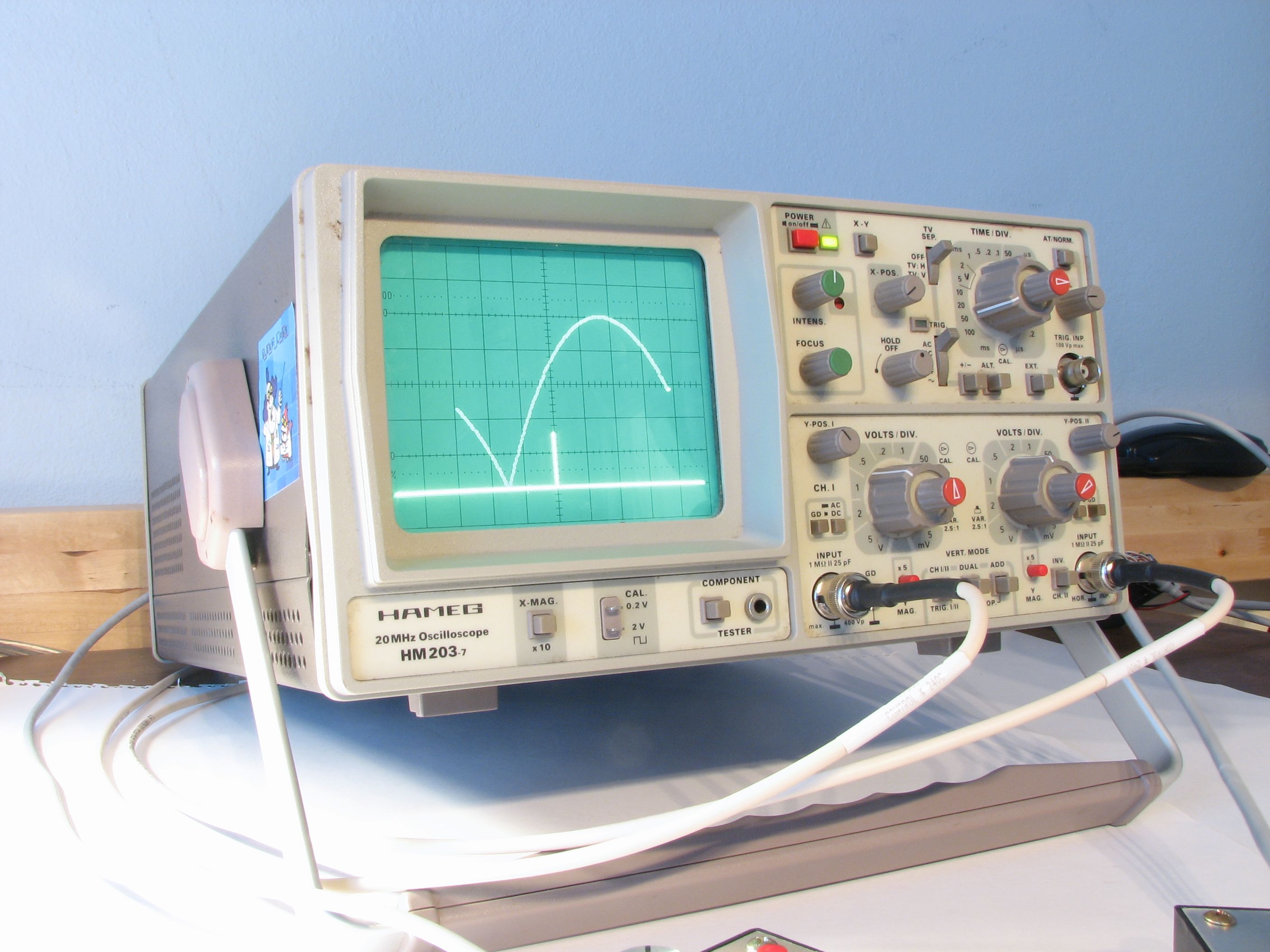
Higinbotham, head of the Instrumentation Division at Brookhaven National Laboratory, designed his game as an exhibit to improve what was an otherwise lackluster visitors’ day at the lab. Tennis for Two presented a tennis court– shown from the side– on an oscilloscope screen, where handheld controllers allowed the two players to toss the ball to each other. Each controller had two controls: a button and a knob. With the button, you could hit the ball at any time of your choosing when it was on your side of the net, and with the knob you could choose the angle at which the ball was hit.
The game was based on the best contemporary technology: analog electronic computers built out of op-amps, relays, and the occasional transistor. It took Higinbotham and his technicians several weeks to design and build the game. Of course, some things have changed over the last 50 years. Using convenient modern electronics, we have designed a functional and playable replica of the original that can be put together by a hobbyist in a couple of evenings. You can watch the video of our recreation on YouTube or embedded here:
So, the next question you might ask is, “How do you build this?” And, if that is in fact what you’re asking right now, you’re in the right place. The quick answer is, “with an oscilloscope, an AVR microcontroller, and a digital to analog converter.” Ready to get going?
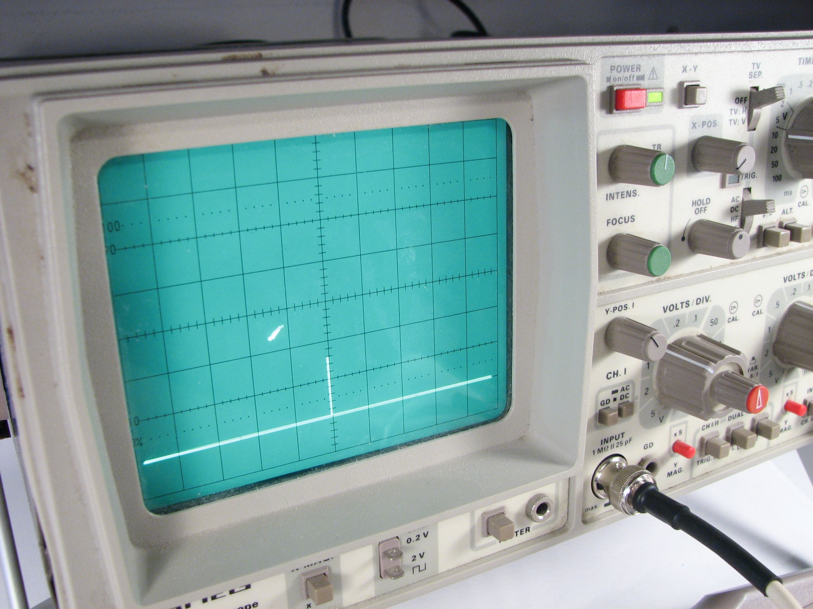
Before we start, let’s be clear that this is not a tutorial in how to build an oscilloscope. Tennis for Two is supposed to display on a ‘scope, so beg, borrow, or buy one if you don’t have one handy. Older low-end analog scopes like mine (a Hameg!) usually go for $50-$150, and if nothing else, you can always make a Scope Clock out of it later.
There are three parts to the electronics that we’re building. First, there is the AVR microcontroller– the brains of the outfit. The specific variety that we’re using is the ATmega168, the same chip used in (for example) the Arduino platform. Secondly, there are two handheld controllers that connect to the ATmega168 microcontroller. Each handheld controller has a knob and a button. Third, there is the digital to analog converter that takes the output from the AVR and uses it to drive the scope.
First, let’s look at the handheld controllers:
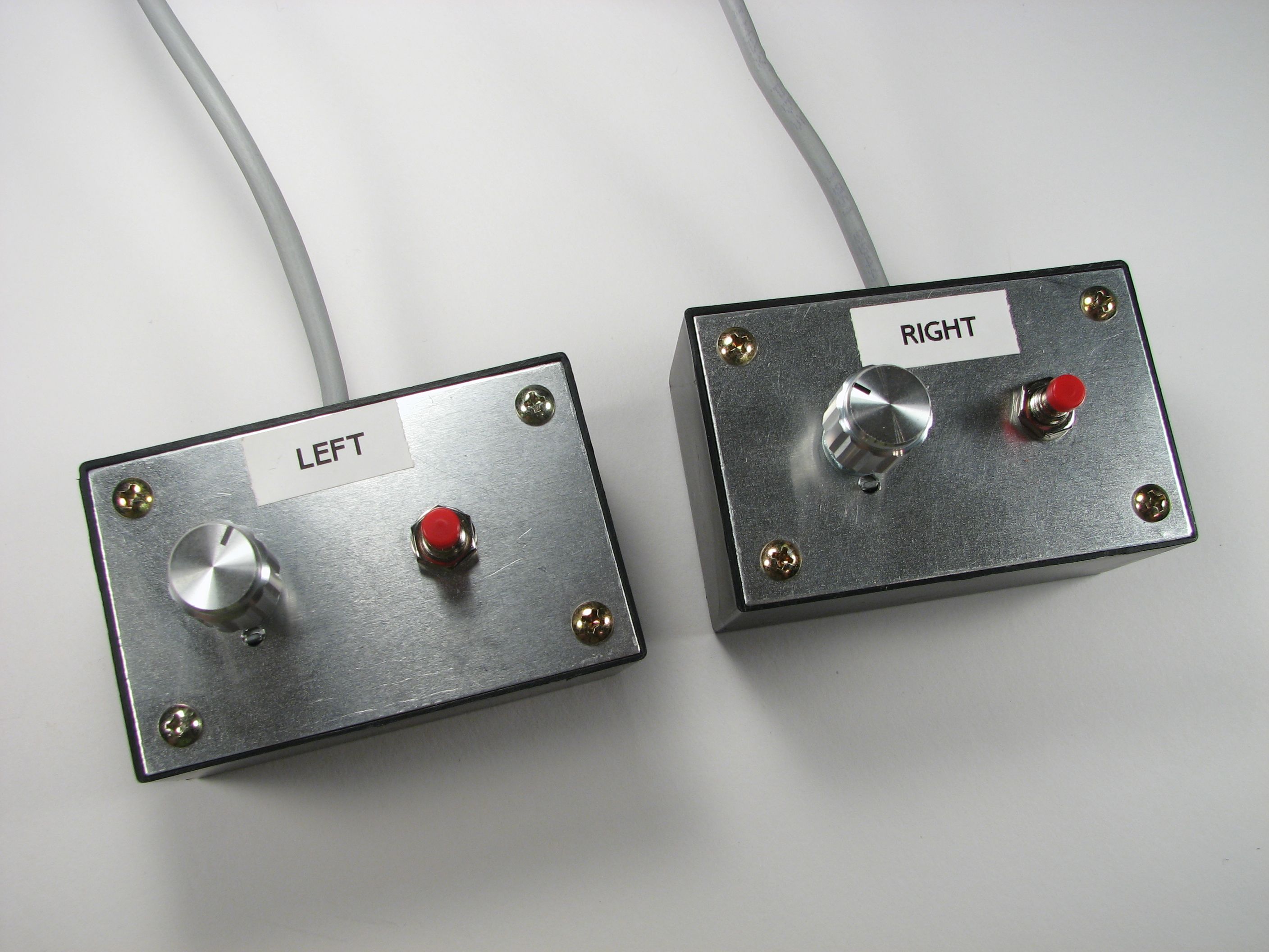
There two controllers are identical little project boxes that each have the button and knob, as well as a cable going back to the other electronics. The controllers themselves are built from 3x2x1″ plastic project boxes with aluminum lids, e.g., Philmore #PB140 or Radio Shack #270-1801. Let’s take a peek inside.
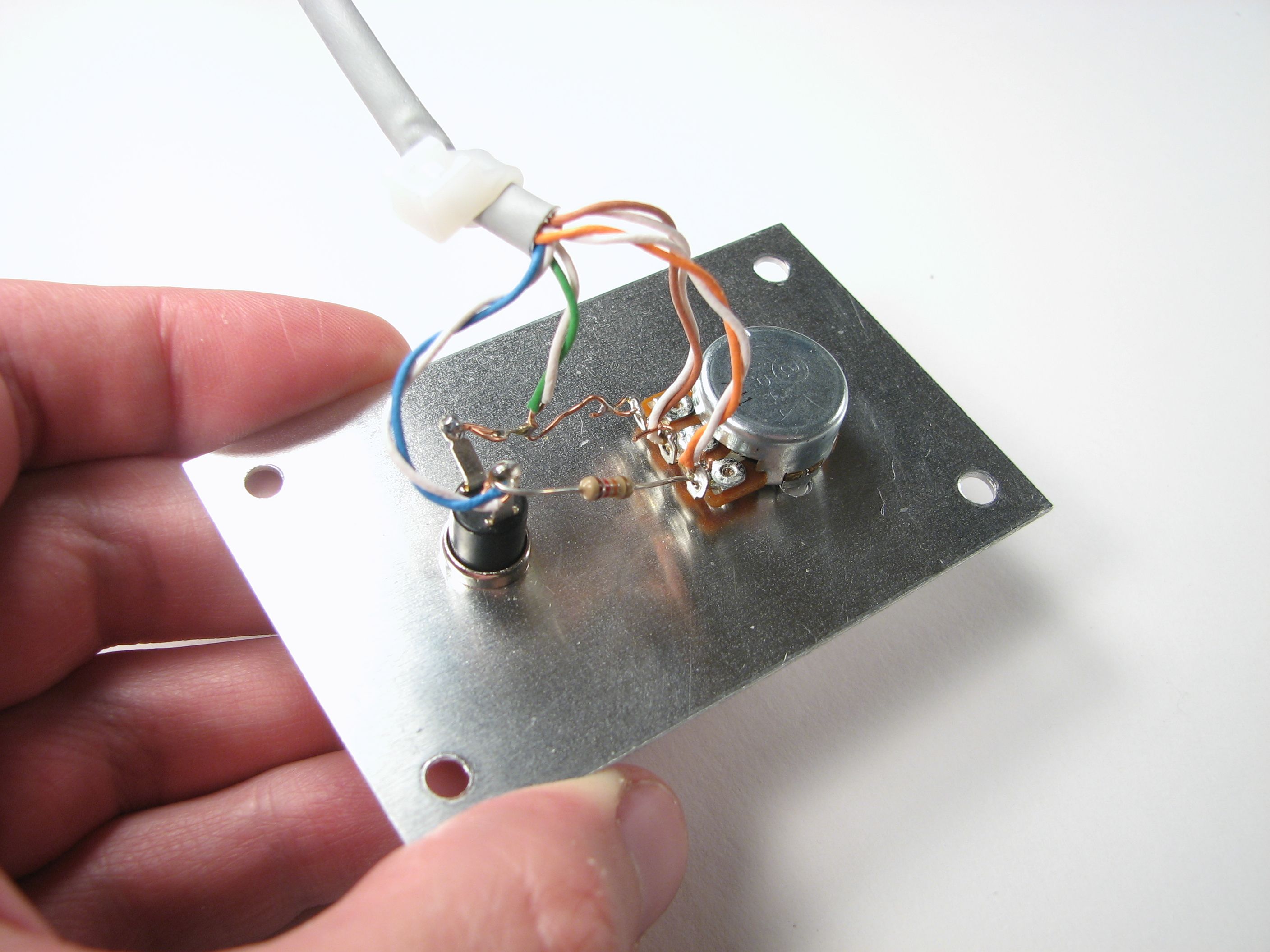
Inside each controller we have a 10k single-turn pot (Jameco #286206) and pushbutton (Jameco #26623). The knob on the pot is a fancy machined aluminum type for extra snazz. (Jameco #138482). The pot is used to vary an output voltage (that controls the firing angle) between 0 and 4.5 V, and the button, when pressed, pulls one of the inputs from 4.5 V down to 0V. (We use an external 10k “pull-up” on the pin to make that happen.) The circuit diagram for one of the controllers looks like this:

To simplify the wiring, we used some old Cat-5 (ethernet) cable as the cables for the controllers. Inside Cat-5 cable are four color-coded twisted pairs: orange, green, blue, brown. For each of these, we stripped and twisted the two conductors together to make four effective (but thicker) color-coded wires. We used orange (+4.5 V) and green (ground) for power, and the other two for signals: brown for the analog knob output and blue for the button switch output.
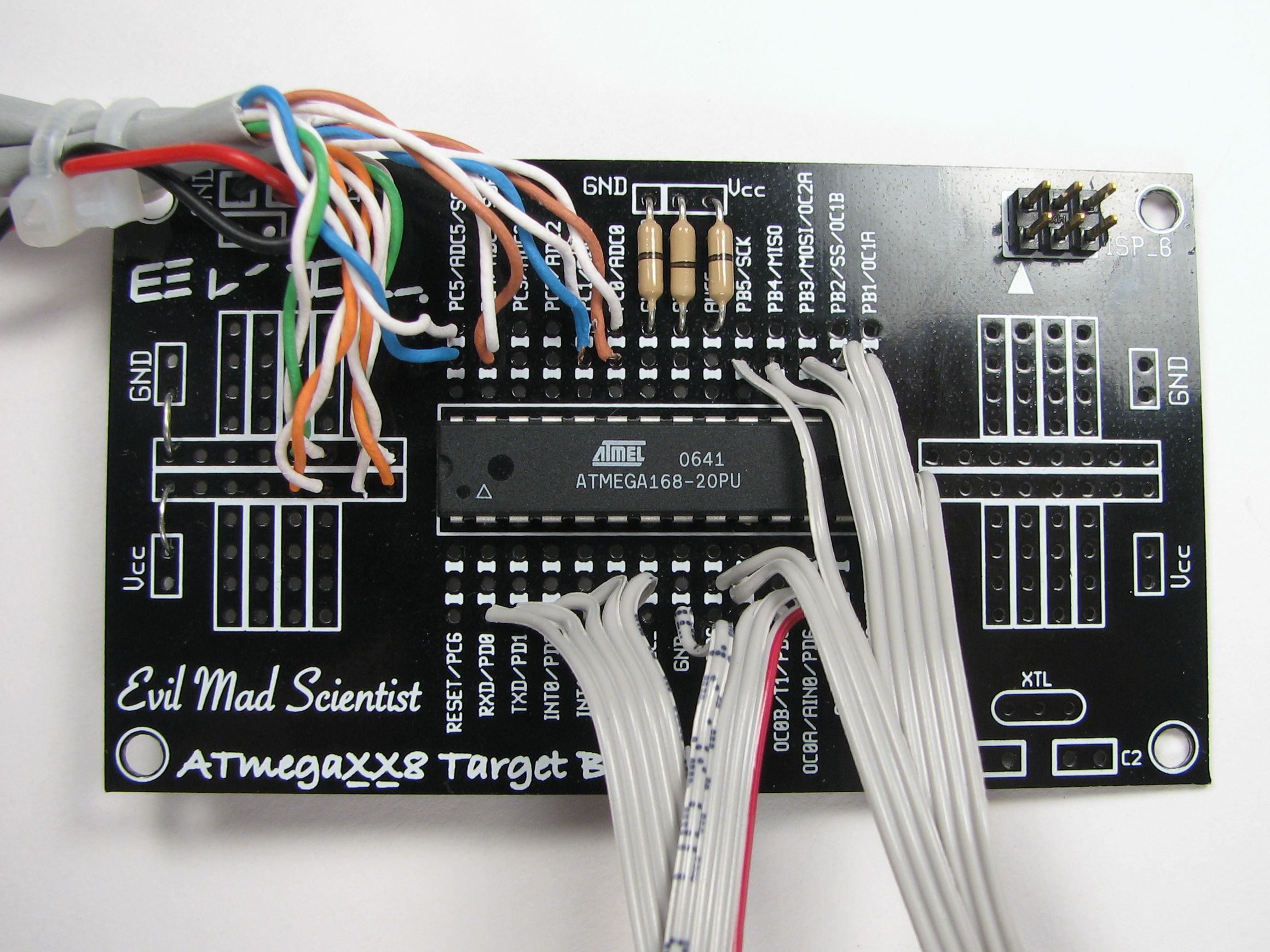
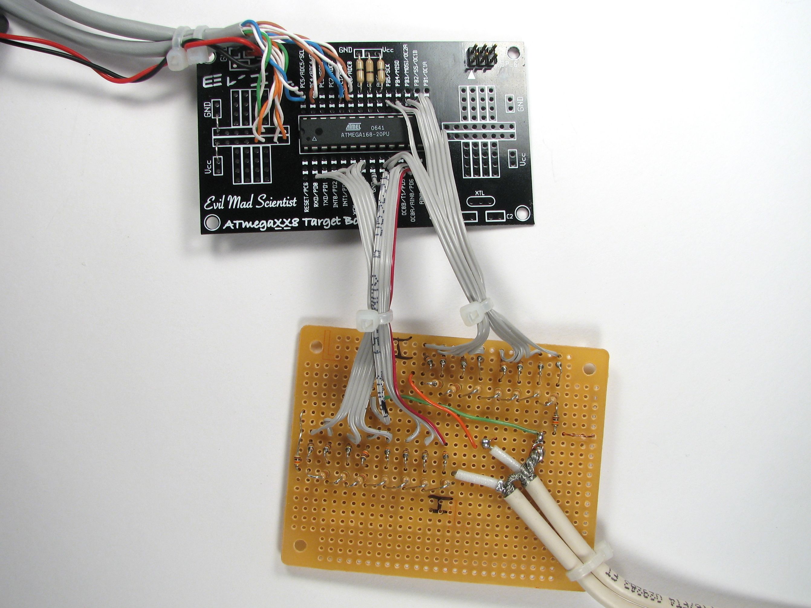
Next, let’s look at the AVR microcontroller:
(This is admittedly messy but it will make sense in a moment. )
To use an AVR microcontroller, we need to provide it with power and ground– usually 3-5 V– and we also need to be able to hook it up to a programmer (at least once). How do do that is described in this article about “minimal target boards” for AVR microcontrollers. I took the easy way out and just used one of our business cards which takes care of the power and programming connections. (The cards are available here),
Power for the board comes from a 3xAA box (4.5 V output). I use a usbtinyisp programer (See review); there are other neat ticks like using an Arduino as a programmer.
Let’s look at a diagram for what else is connected to the microcontroller:

We’ve already discussed how the power and programming pins come into play. The other two things to notice are the connections for the handheld controllers and the digital outputs. The blue and brown lines from the two handheld controllers hook up as shown, and the power and ground (orange and green) lines to the handheld controllers also get hooked up to the power and ground pins on the AVR, or anywhere on its target board.
The remaining pins labeled on the diagram of the microcontroller are the 16 digital output lines: PB0 – PB7 and PD0 – PD7. These two eight-bit output ports will be used to control the output that goes to the scope– the “PB” outputs will control the “X” position and the “PD” outputs will control the “Y” position of the oscilloscope beam. But, the scope takes analog outputs and these signals are digital. So, what we need next is a
digital to analog converter (DAC).
For our DAC, we used a very simple and forgiving topology, the so-called R-2R scheme with 8 bits of resolution. When compared with the other (cheap) method of making a DAC on an AVR, the advantage of this scheme is that it has higher frequency performance– a big plus for drawing clean dots on our scope screen. On the down side, it is a little more tedious to build and has only 256 resolvable levels. Still, a 256 x 256 grid turns out to be just fine for playing games on the scope screen. (See also this article about building a R-2R DAC on an Arduino Protoshield.)

Each of the R-2R chains is composed of nine 10k resistors and seven 5k resistors. (Note the name “R-2R”– you can actually vary the values a bit as long as you keep the ratios and locations the same– e.g., nine 20k resistors and seven 10k resistors should also work fine.) To actually hook this up, we brought the PB and PD signals over onto a new piece of perfboard with a couple of ribbon cable segments, so that we’d have room to set up all of our resistors:
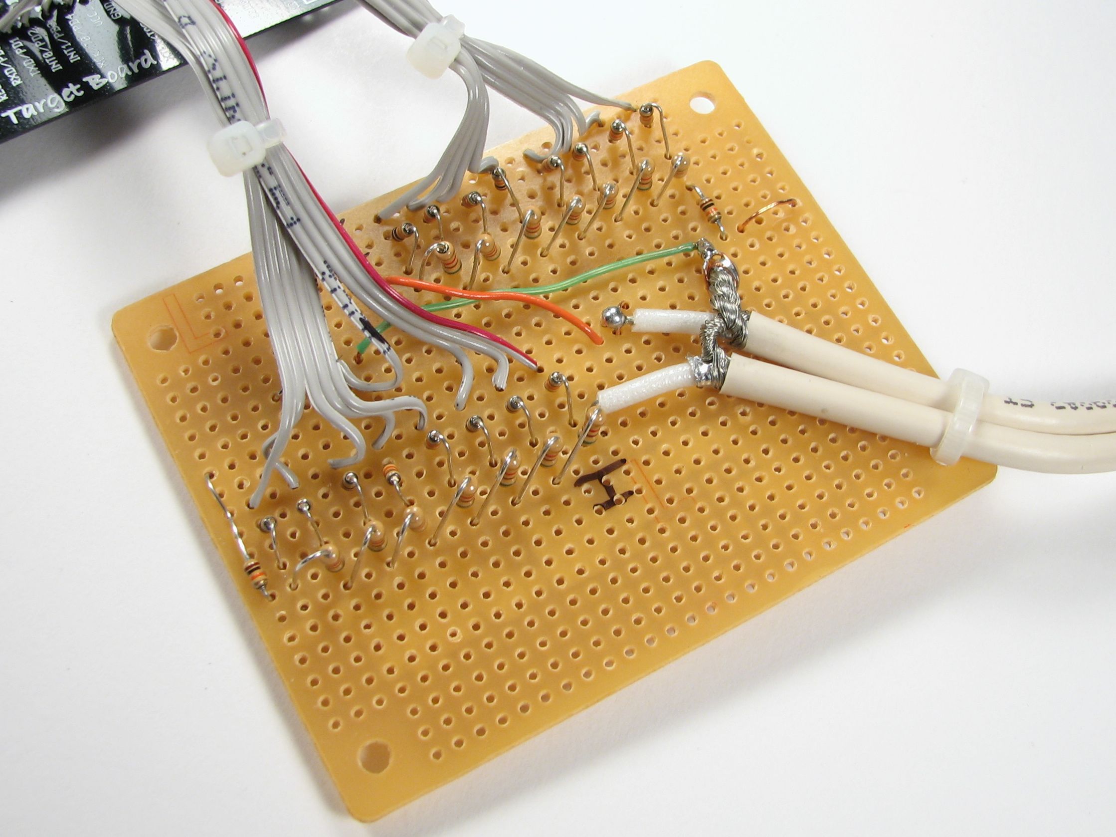
The output of each R-2R chain goes to a BNC cable that hooks up to the scope. Because we actually need two BNC inputs to the scope, we used one single BNC cable, cut in half and stripped. Be sure to hook the shielding braid of the BNC cables up to the ground of your circuit.
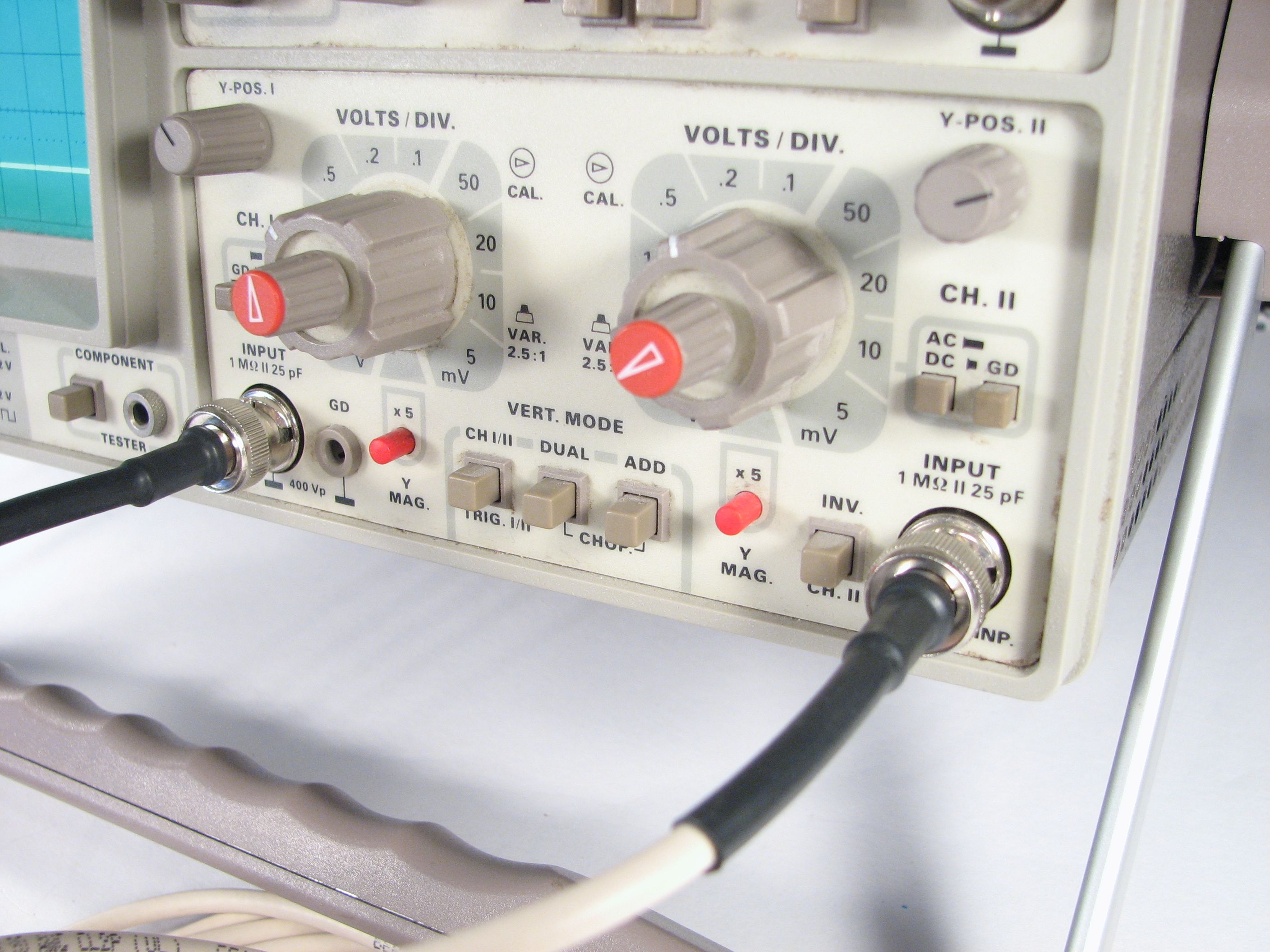
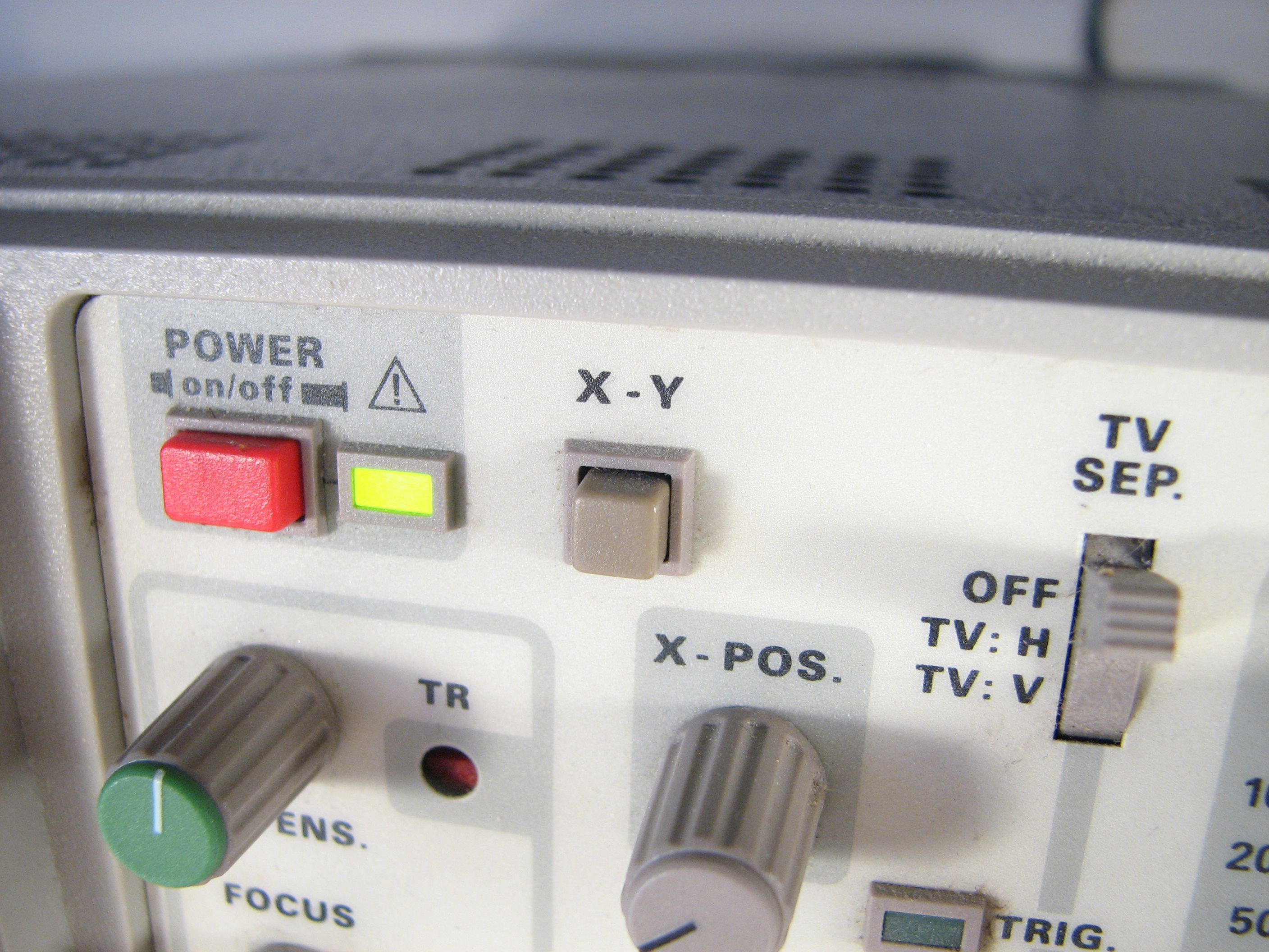
And then as the last hardware step, hook the two BNC outputs of the R-2R chain up to the scope and put the scope in X-Y mode.
The firmware for the AVR is being released under the GPL. You can download it here (6 kB .ZIP file) and install it through your favorite interface.
That’s it– you should be good to go. You will need to adjust the X and Y offsets and scales on the scope so that the court and ball show up where they are supposed to. And, if you are so inclined, there are plenty of parameters and routines to mess with in the source code.
Finally, special thanks to Grow-a-Brain where we first heard about this wonderful game. We wouldn’t have built it if we hadn’t found out about it in the first place. :)
I’d be the coolest technician in the building if I brought this thing in to show off. Now I just have to find a suitable PONG project for the AVR as well!
most bad ass music. ever.
Thanks! (Haven’t picked up my guitar in years!)
—
Windell H. Oskay
drwho(at)evilmadscientist.com
http://www.evilmadscientist.com/
I did something similar about 6 years ago for my physics electronics lab. My partner and I did something pretty close to Pong and it was all analog signals generated on-board. Plug-and-play baby!
This game looks really cool. Is it possible to modify it to work on a TV?
I’m sure it’s possible, but it would require a new output circuit to be added. The oscilloscope is a vector display, whereas the TV is a raster display– this is like the difference between the vector and raster displays used for (e.g.) Asteroids versus Space Invaders.
—
Windell H. Oskay
drwho(at)evilmadscientist.com
http://www.evilmadscientist.com/
Hi Windell. I have a PIC microcontroller based pong game. You can find the schematic here: http://www.velleman.be/downloads/0/manual_mk121.pdf It seems like the output circuitry is nothing special. Wouldn’t that be possible with an AVR microcontroller?
It’s certainly possible. The difference is that Pong was (more or less) intended to run on a TV and Tennis For Two was intended to run on a scope. :)
—
Windell H. Oskay
drwho(at)evilmadscientist.com
http://www.evilmadscientist.com/
Oh, I see. But if it can be done in a simple way, then is it possible that you could show how to do it? I’m sure there is many others who would like this cool game.
analog electronic computers built out of op-amps, relays, and the occasional transistor
Uh, aren’t op-amps usually comprised of transistors?
The “standard” op-amp in 1958 was a tube op-amp. The first commercially available solid state op-amps weren’t out until 1961. Commercial transistors had only been available since about 1954, and were probably still rather novel devices.
Even so, just because IC op-amps are made out of transistors today doesn’t mean that saying op-amp and transistor are redundant– it’s very common today to build circuits with both op-amps and discrete transistors.
—
Windell H. Oskay
drwho(at)evilmadscientist.com
http://www.evilmadscientist.com/
Understood. My point is I think it would be weird to build a circuit out of tube op-amps and the occasional transistor, as you suggest. I wonder if the original circuit is available anywhere.
Nice. Any chance of SPACE WAR(S) now?
I’m not sure that it’s as necessary– We saw spacewar at a video game show that we went to this month. It’s apparently not nearly as lost as Tennis for Two was.
—
Windell H. Oskay
drwho(at)evilmadscientist.com
http://www.evilmadscientist.com/
Would it be possible to get this awesome game working on a TV. If so, could you then post the schematic and code? Sorry, I’m new in programming.
Hey!
Very nice project. I want to build this circuit. Am I right in thinking that you can also use an ATmega8 microcontroller?
There’s only half of the flash and it doesn’t provide such high frequencies but that shouldn’t be a problem. Do I miss something?
Thanks for your help.
Cheers
Matthias
I think that it should work fine.
I don’t remember what our code size is off hand, but if it doesn’t fit in 8k, it could be made to with slightly better coding.
—
Windell H. Oskay
drwho(at)evilmadscientist.com
http://www.evilmadscientist.com/
Hey!
Ok I compiled it and the size of the hex file is round about 11 kB.
By the way compiling for atmega8 fails as there is no PRR (Power Reduction Register).
tennis.c:186: error: ‘PRR’ undeclared (first use in this function) –>
//PRR &= ~(_BV(ICF1)); //Allow ADC to be powered up
Is this piece of the source code obligatory? Or is there an equivalent for use with atmega8?
(But as far as it’s 11 kB there’s imho no sense for use with this uC at the moment. ^^)
So far thanks for your help!
Kind regards,
Matthias
I think that the PRR (power reduction register) is not on the ATmega8; it’s a feature that reduces the power requirements for the ADC. So… it should work without it.
As far as the memory requirements, we’ve done some things that are pretty wasteful of memory space because we had extra– like putting the whole sin() and cos() functions in memory instead of pre-calculating the table.
None the less, and although the .hex file is big, what actually gets programmed to the chip might fit anyway. When we program it to the chip, avrdude reports "6880 bytes of flash verified." So it might be worth a try, even without additional modifications.
—
Windell H. Oskay
drwho(at)evilmadscientist.com
http://www.evilmadscientist.com/
What is the resistance of the 3 jumpers?
They are "jumpers" — so zero ohms, effectively– they are just wires connecting power to the analog power supply pins of the chip.
—
Windell H. Oskay
drwho(at)evilmadscientist.com
http://www.evilmadscientist.com/
So I could basically use plane wires?
No, there’s nothing special about these wires.
—
Windell H. Oskay
drwho(at)evilmadscientist.com
http://www.evilmadscientist.com/
Is low, low or is high, low when you do the potentiometer?
No idea; it’s been a while. Try it out. If it feels backwards, switch the two non-wiper terminals on the pot.
I *think* that the two pots should be wired oppositely, that is, so that the controllers are different. If that’s the case, then all you need to do is label L & R *after* you try them out.
—
Windell H. Oskay
drwho(at)evilmadscientist.com
http://www.evilmadscientist.com/
Has anyone tried adding a direction vector indicator to show which way the energy of the paddle is pointing?
The knob on the controller has a mark that indicates the direction.
—
Windell H. Oskay
drwho(at)evilmadscientist.com
http://www.evilmadscientist.com/
Please seriously :) consider adding a fresnel lens screen magnifier. Terry Gilliam (ala Brazil) would approve. :)
What is the difference between ATMEGA168-20PU and ATMEGA168-20PI? I saw a pack of 14 PI for $40 but the PU are 2 for $20. both with free shipping.
I’m not sure where you saw these; the prices are usually about the same for the two versions. The -PU version is the lead-free one.
Windell H. Oskay
drwho(at)evilmadscientist.com
http://www.evilmadscientist.com/
See what I mean?
http://cgi.ebay.com/Atmel-ATMega168-20PI-NEW-Tube-14-/230490955598?cmd=ViewItem&pt=LH_DefaultDomain_0&hash=item35aa54df4e
http://cgi.ebay.com/2-pcs-ATMEGA168-20PU-MCU-AVR-28DIP-ATMEGA168-20PU-NEW-/390151716941?cmd=ViewItem&pt=LH_DefaultDomain_0&hash=item5ad6dac04d
How to I compile the source code to hex is there a hex file I can download?
We never work with hex files directly; it leads to too many device-dependent issues. This code is for use with AVR-GCC, and the included makefile knows the commands to do that.
It’s just
make all
then
make install
to compile and install it; you may need to edit your AVR device and/or the programmer that you use.
Windell H. Oskay
drwho(at)evilmadscientist.com
http://www.evilmadscientist.com/
Hey Man,
Nice achievement!
Can you please show a complete schematic rather than just parts
and what diemensions was the oscilloscope screen? (160×200, 300×340 etc.)
replying to this will be a previlage.
from,
~Herr Drake.
If we put all three drawing parts on the same page and labeled it a "complete schematic," it would still consist of the three drawings and you’d still have to connect wires between the named pins. So, I’m not sure what benefit there is. A number of people have been able to build this from our design, I suspect that you can as well.
The scope is analog; it doesn’t have any pixels or set resolution.
Windell H. Oskay
drwho(at)evilmadscientist.com
http://www.evilmadscientist.com/
Does this require a dual channel oscilloscope? I’ve actually been having trouble locating an oscilloscope, I haven’t found any listed with Home Depot or Lowes, and the guy at my local hardware store didn’t even know what I was talking about. I would prefer an older style oscilloscope closer to what William Higinbotham used for the original 1958 machine. In fact, I want to make my build as historically accurate as I can. I managed to find a 1970s oscilloscope up for auction on ebay, hopefully I can win it…
This uses the scope in X-Y mode. That requires two inputs, but doesn’t need all the modern feature of multi-trace scopes– there’s only one beam.
Windell H. Oskay
drwho(at)evilmadscientist.com
http://www.evilmadscientist.com/
You would never have found an oscilloscope at a hardware store like Lowes or Home Depot, probably not even at a Radio Shack. You find them at professional electronics store or online catalog, like digikey.com
They’re actually rather obsolete now, I think most engineers use data recorders hooked into a PC.
>They’re actually rather obsolete now, I think most engineers
>use data recorders hooked into a PC.
Scopes are *far* from obsolete. PCs have made chart recorders obsolete, though. ;)
The capabilities of modern scopes are vastly beyond those of PC data recorders. Fast triggering, high-resolution analog sampling, low noise, long waveform capture, high bandwidth and the ability to examine and tweak up signals of interest with dedicated knobs are features that engineers value dearly.
Yes, you can get "pc oscilloscope" boxes, but they generally don’t have higher performance per dollar than "real" scopes, and the real-world performance is typically much lower. There is no more hostile environment for analog signal analysis than the inside of a PC, and USB isn’t much better.
Windell H. Oskay
drwho(at)evilmadscientist.com
http://www.evilmadscientist.com/
if you don’t have a scope could you edit the code to make it run on the pc without the scope hardware or software?
Well, yes, but you’ll be using very little of the code– most of it is to deal with the microcontroller and its interfaces.
Windell H. Oskay
drwho(at)evilmadscientist.com
http://www.evilmadscientist.com/
http://cgi.ebay.com/Arduino-Duemilanove-2009-AVR-ATmega168-20PU-USB-board-/360309203790?pt=LH_DefaultDomain_0&hash=item53e41a234e
Is this a good programmer? how I use it?
Would the game code work with the atmega328p-pu? I hear it’s better then the atmega168-20pu.
Yes it will work, but it’s a minor waste of resources. The ‘328 has twice the memory of the ‘168 (but is otherwise the same in terms of capability), and this fits into the memory of the ‘168.
Windell H. Oskay
drwho(at)evilmadscientist.com
http://www.evilmadscientist.com/
If I wanted to could I use the 368 instead for the game?
opps meant to say 328.
As I said, "yes it will work."
Windell H. Oskay
drwho(at)evilmadscientist.com
http://www.evilmadscientist.com/
>If I wanted to could I use the 368 instead for the game?
Possibly; I’m not familiar with that chip– you’ll have to check its datasheet to see what it’s capable of.
Windell H. Oskay
drwho(at)evilmadscientist.com
http://www.evilmadscientist.com/
What is the the lowest oscilloscope required to read the game? If I have an oscilloscope that can read waves at 1 Khz max would that work or does it have to be a lot higher? Could you mod it to work with 1 channel scopes or does it have to be 2 channels?
Should be at least 8 MHz, two channel, and capable of XY mode.
Windell H. Oskay
drwho(at)evilmadscientist.com
http://www.evilmadscientist.com/
Hi, I want to build the game, and wanted to ask
What values of the code do I have to change to make the ball faster?
I have a programmer TopMax to program the microcontroller:
http://www.eetools.com/index.cfm?fuseaction=product.display&product_ID=301&ParentCat=17:
How I can compiled the code for use?
excuse my English, I do not speak English, is the translator.
Thanks.
I found the schematic of the original with a quick google:
http://www.computerspacefan.com/TennisForTwo.htm
and a longer article including some notes and the schematic by Higginbotham:
http://www.bnl.gov/bnlweb/history/higinbotham.asp
Ian
i got this kit with a pre-programmed chip and my line on the bottom is more like the dotted yellow line on a road.. i used 1/8th watt resistors 4.7k and 10k. maybe i did something wrong? i have a lot of experience with soldering so i know that is good. i also used solid wire to go from the 2 boards if it is too much. my wires are as short as i can make them.
here are pics of my tennis for two. i used rca’s as the x-y connections to my tennis for two console and if you look under the wire under the rca i used a 1/8th mono jack as the power from my 5v power supply.
http://i53.photobucket.com/albums/g49/pimpmaul69/my11.jpg
http://i53.photobucket.com/albums/g49/pimpmaul69/my3.jpg
http://i53.photobucket.com/albums/g49/pimpmaul69/tft2.jpg
http://i53.photobucket.com/albums/g49/pimpmaul69/tft1.jpg
http://i53.photobucket.com/albums/g49/pimpmaul69/tft3.jpg
Hello, nice work, some one can help me to find the code inside de ARM?? I want to create this project in a pic.
thxs
No ARM in this project. ;)
Windell H. Oskay
drwho(at)evilmadscientist.com
http://www.evilmadscientist.com/