


In February we gave a sneak preview of our project to construct a home-built three dimensional fabricator. Our design goals were (1) a low cost design leveraging recycled components (2) large printable volume emphasized over high resolution, and (3) ability to use low-cost printing media including granulated sugar. We are extremely pleased to be able to report that it has been a success: Our three dimensional fabricator is now fully operational and we have used it to print several large, low-resolution, objects out of pure sugar.

The general idea of our build process– that of stacking solid two-dimensional printed layers– is actually common to most solid freeform fabrication methods. Our machine employs what we believe is a fairly novel low-cost technology to accomplish this: selective hot air sintering and melting (SHASAM).
The printing process begins with a bed of a granular printing media that has a fairly low melting point. Using a narrow, directed, low-velocity beam of hot air, we selectively fuse together the print media, forming a two-dimensional image out of the fused grains. We then lower the bed by a small amount, add a thin flat layer of media to the top of the bed, and selectively fuse the media in the new layer, forming a two dimensional image that is also fused to any overlapping fused areas in the layer below. By repeating this process, a three-dimensional object is slowly built up. At the end of the build, the bed is raised to its original position, disinterring the fabricated model, while unused media is reclaimed for use in building the next object.
Our process is very much like a low-cost version of Selective Laser Sintering, or Selective Laser Melting, which are commercial processes used for plastic and direct metal printing. Rather than using a high-power CO2 or YAG laser ($5k and up), we use hot air created with the help of a $10 heating element.
Trading off a laser for a heat gun gives us lower resolution but at much lower cost, and is typical of our approach to 3D fabrication. We have taken a very different approach from most other fab projects (e.g., Fab@Home and RepRap) in that we have a comparatively large printable volume, but less need for precision and high resolution.
Our fabricator is not designed for prototyping machine parts; it’s designed for fun, for large-scale 3D illustration, for sculpting, architectural models, and other applications where resolution isn’t the only important factor.
We estimate the total cost to build a machine with similar capability to be in the neighborhood of $500. Realistically, the cost of any project like this is not a fixed number, and since recycled components are involved, the actual cost could range up or down by a factor of two depending on how resourceful the builder is.
There are a number of different print media that may be suitable for use with SHASAM fabrication: many types of plastics and waxes have low melting points and are available in granular or powder form. Beyond that, there are a number of interesting foods– chocolate chips come to mind– that can be used with the process However, one of the most interesting possibilities is using table sugar.
Granulated Sugar: low cost print media
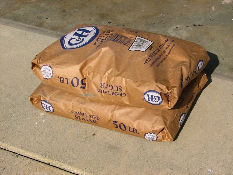
As we mentioned in our preview of the printer, our printing medium of choice is granulated sugar. Sugar is a particularly good medium because it’s non-hazardous, non-toxic, non-intimidating, kid friendly, water soluble, rigid despite having a low melting point, and as an organic, may be suitable for making forms for investment casting.
It’s also very easy to obtain and very inexpensive: you can buy it at grocery stores, and in large bags at places like Costco for about $0.37/pound.
The price of sugar compares quite favorably to the polycaprolactone (a low melting point polyester) used by the reprap project which costs about $4.00 a pound. As it turns out, even $4.00 per pound is quite inexpensive compared to the media for many other solid freeform fabrication systems.
Beyond just lowering the media cost of a given fabricated object, using a low-cost medium can be leveraged to make large-volume printing both practical and economical. Our fabricator has a maximum printable volume of 24 x 13.5 x 9 inches (61 x 34 x 23 cm)– 2916 cubic inches, or 1.7 cubic feet, and holds a little more than 100 pounds of sugar, which costs about $37 retail.
Of course, the direct media cost in the models can also be an important consideration. Consider this model of a wood screw that we fabricated out of sugar: It’s 20 inches long, with the head diameter of 4.5 inches, and it weighs about 2.5 pounds, so the total media cost is about $0.93.
For a fun exercise, look up how much it would cost to make a similar model on a prototyping industry standard $20,000 Dimension ABS 3D printer– if it could print objects anywhere near that big.
(Hint: it’s more than $0.93.)
Mechanics and Electronics
The big idea of the mechanical system is that we take a hot air gun and move it around a bed of sugar, selectively fusing a set of points before lowering the bed of sugar and adding a new layer.
Our hot air gun is based upon the design of a hot air rework station. However, we have heavily modified it, and learned how to make an equivalent system inexpensively. The heater design now essentially consists of a 500 W, $10 air heating element and a small air pump– a $5 aquarium air pump works well. At a minimum, use of the heater element requires a housing to be constructed, the air pump and a control system that can provide a the chosen amount of power to the heating element. We have seen that the element can be driven directly from 120 V, with duty cycle controlled by an inexpensive digital relay. The heater element is hardly new technology; it’s the baby sister of the one in your hair dryer. None the less, it’s well designed and quite suitable for this application.
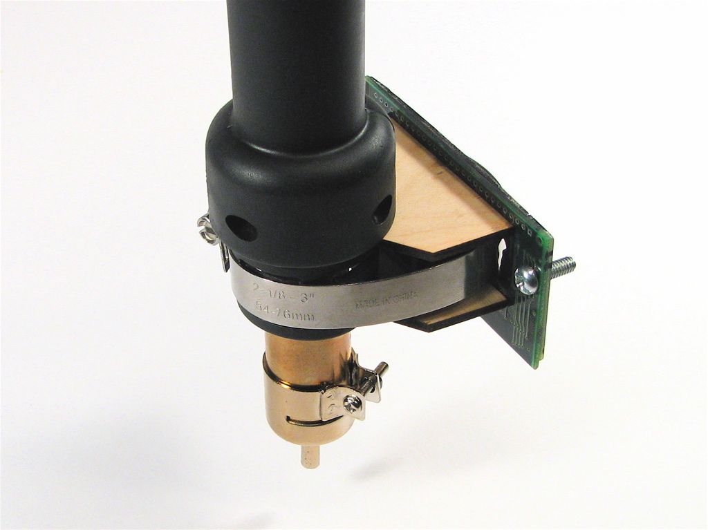
Thus far, we are still using the bulky original housing from the hot-air station itself, but plan to design a replacement head and nozzle when time permits. The existing housing has a slightly odd shape so we made this mount to attach it to the carriage of our X-Y motion control system.
The original head was not designed to operate at both high temperature and low air flow; it tends to overheat easily. One improvement that we made that has been hugely beneficial is to mount a cooling fan right next to this structure, keeping it cool on the outside while in use.
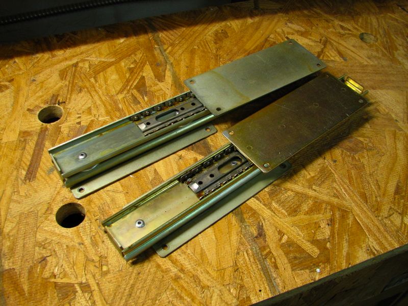
The X and Y axis motion control systems are based on belt drives and quadrature-encoded motors recycled from two old HP plotters, a large one and a small one. This is one of those places that your resourcefulness can save you a lot of money: The number of old-generation inkjets and plotters out there is truly stunning– go find a couple, and make them do something useful again.
In order to control the quadrature-encoded motors that came on our printer parts, we designed custom digital servo circuits that cost about $10 each to build. The circuits are based around a high-power analog output stage and an AVR microcontroller that accept position commands. The position commands are sent using a higher precision version of standard hobby servo PWM control code, where the position command is encoded in the width of a positive pulse between one and two milliseconds long. We will be writing up and releasing the hardware design as well as the source code (under the GPL) for these servo controllers in the near future.
The hot air gun is mounted to the belt-driven carriage on the Y axis of the printer. The Y-axis belt-drive system is mounted, on one end, to a linear bearing that slides along a steel rail. That bearing is pushed by the belt-driven carriage on the X axis, through a rubber band low-cost flexible rubber coupling. The other end of the Y-axis belt-drive system is supported by a free-rolling rubber wheel from the hardware store.
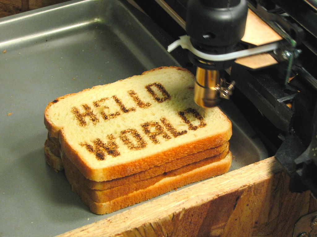
For our operational tests and a demonstration of the XY motion control system last month, we mounted the hot air gun to the system and placed a piece of bread where the sugar would normally go– allowing us to make CNC (computer numerically controlled) toast, demonstrating successful control of both the hot air gun and the X and Y motion control systems.

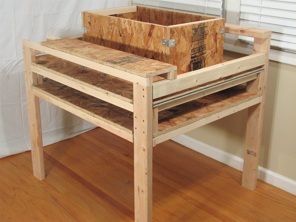
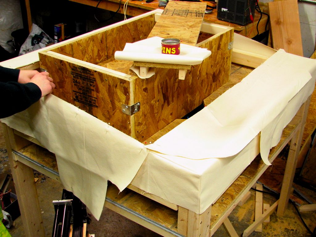
The fabricator primarily consists of a large wooden base, which was designed in Sketchup. It was designed to hold the X-axis belt drive system on the front side and provide a back platform for the rubber wheel to roll along. It also provides elevation above the floor and holds the box that defines the walls of the build region.
Here you can see the model as drawn in Sketchup, and the base that we constructed from that model. If you want to take a closer look, you can download the model
here. (144 kB ZIP archive of sketchup .skp document)
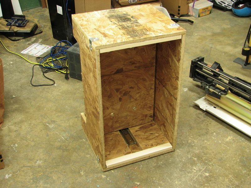
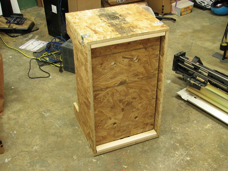
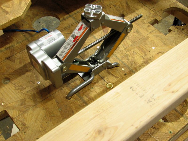
Since the vertical axis must be able to easily raise up the bed containing all of the sugar– potentially more than 100 pounds– it needs to be a bit tougher than a printer carriage. The vertical motion is constrained by a five-sided wooden box with a floor that can move up and down on a set of drawer slides. The motor for the vertical motion, which pushes up on the floor of the wooden box, is actually a modified one-ton electric automotive jack that has been converted into a (large scale) hobby servo motor.
Besides the three motion axes, there is also a heater controller that is used to control the power delivered to the hot air heating element. Together, the four controllers (X,Y,Z, Temperature) require four axes of computer control.
Canvas Liner
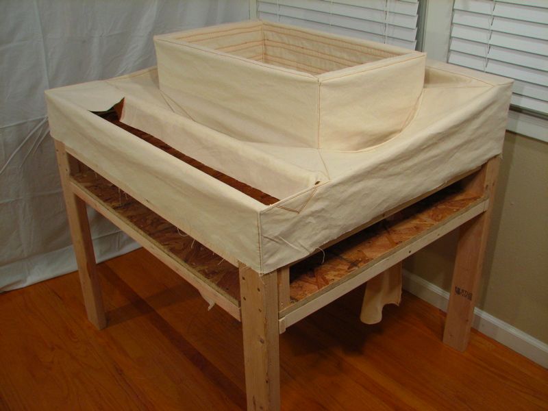
Wrapped around the wooden base is a flexible canvas liner that prevents sugar from leaking out in strange places and assists in recovering unused media. Canvas is a good choice for this application because it is strong, durable, woven tightly enough to contain granular media like sugar, and washable.
We got ours at a fabric store for $7/yard, in 60-inch width, and we needed about five yards. If you’re trying to save costs, you might be able to do better elsewhere, e.g., buying canvas drop cloths intended for painting.
The liner was designed to hold the sugar in place during forming, and to channel the excess into buckets for reuse after raising the platform.
The canvas liner fits snugly around the bin, and the inner part folds up accordion-style to accommodate raising and lowering the piston.
The pleats are reinforced with interfacing to assist with folding. The upper edge and the bottom surface are attached to the bin with velcro. The outer part of the canvas fits around the frame, and tapers in to meet the bin, forming funnels that catch sugar and feed it into buckets below.
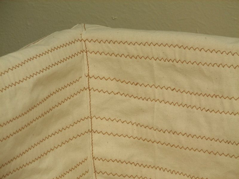
Figuring the sizes for most of the pieces was straightforward working from the measurements from the sketchup model. However, the tapering portions for the funnels were cut large, pinned in place, and then sewn and trimmed.
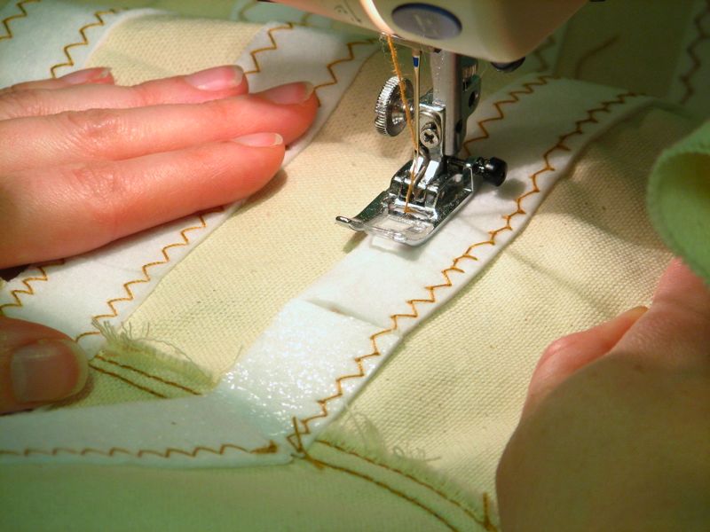
Seams were generally folded and reinforced in such a way that the sugar flows downward easily. Sewing was done with a home sewing machine with heavy duty thread usually used for denim.
Software
There are several different layers to the software needed to control a three-dimensional fabricator, and they are implemented in our system with a variety of different techniques. We begin with a 3D model generated in (or imported into) POV-Ray, and then render the POV-Ray image as a set of two-dimensional bitmaps of slices through the image. The bitmaps are generated in such a way that they directly represent which points will, or will not, have the printing medium fused. We then take the bitmaps and use them to “draw” with our hot air gun at all of the black points on the bitmap.
Here is one of our 3D models, along with one of the generated 2D bitmap slices through that object:


You can download the 3D model, both the POV-Ray document, the rendered and sliced versions here. (53 kB ZIP archive)
Operating the 3D fabricator requires precision motion control in three directions, which is potentially difficult. Computer control and interface are provide through a MAKE Controller.
Presently we are using an old student version of LabVIEW to control the MAKE Controller– reading in a 2D bitmap, parsing it into a simple rastered toolpath, and converting that to position commands, sent to the MAKE Controller using UDP packets. Labview is, of course, not free software, and any suggestions about open-source solutions that would do the job nicely are welcome. (PD and Processing seem like possible directions, but we’d like to hear what you think in the comments.)
While the Make Controller has many remarkable capabilities, we are hardly taking advantage of them here; it is strictly acting as a computer-controlled device to output four servo-motor control code signals. Budget conscious builders may want to instead consider using a dedicated servo controller, like this Micro Serial Servo Controller, from Pololu, a precision 8-channel servo interface starting at $17.95.
Making things with the fabricator
Now that we’ve got all our parts together, let’s fab some sugar objects.
The effective horizontal resolution of our fabricator is presently limited to around 2 mm by the very one-point-oh design of our hot air nozzles, but can in principle be made much higher even while using granulated sugar as the print medium. The resolution is determined by a number of factors, including the air nozzle size, the air temperature and flow rate, and (obviously) the position step size in the three directions. Printing at a higher resolution takes longer, so we have actually been operating it in a low-resolution mode in order to produce some sample objects– quickly– before the Maker Faire. All of the objects on this page were made with pixel (well, voxel) size 2.5 x 2.5 x 2.7 mm (10 x 10 x 9 DPI), where the 3D models have been properly quantized to account for the larger vertical step size. Even at this low resolution setting, the total number of printable points in our fabricator is over 2.6 megavoxels.
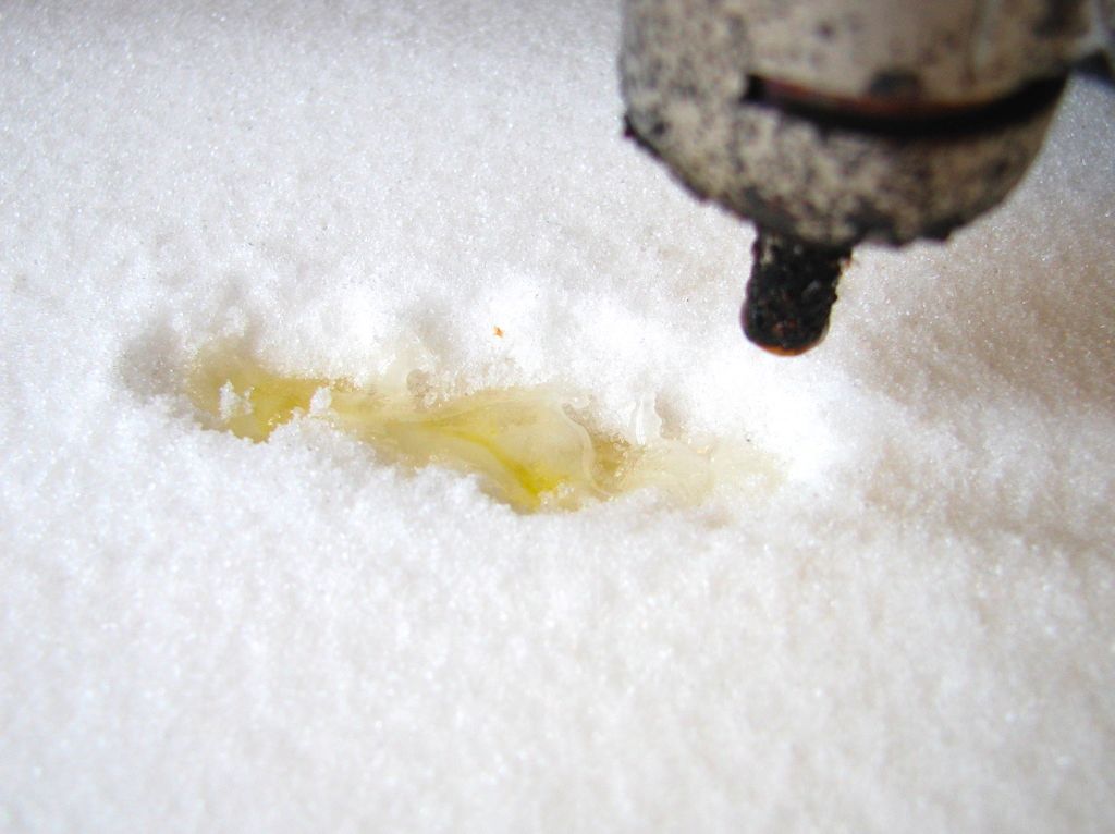
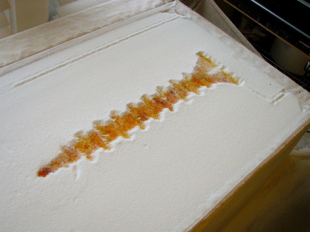
Here is the first step: Drawing a thin line with the heater element, fusing the sugar together. The width of the line drawn in the picture here is about 3 mm, and so is a little wider than our minimum pixel width.
For each pixel that we want to fuse, we hold the hot air gun over that point for a period of time, typically between one and three seconds, depending on air temperature settings and the thickness of the layer that we want to fuse. (We should be able to reduce that time with a better hot air nozzle design.)
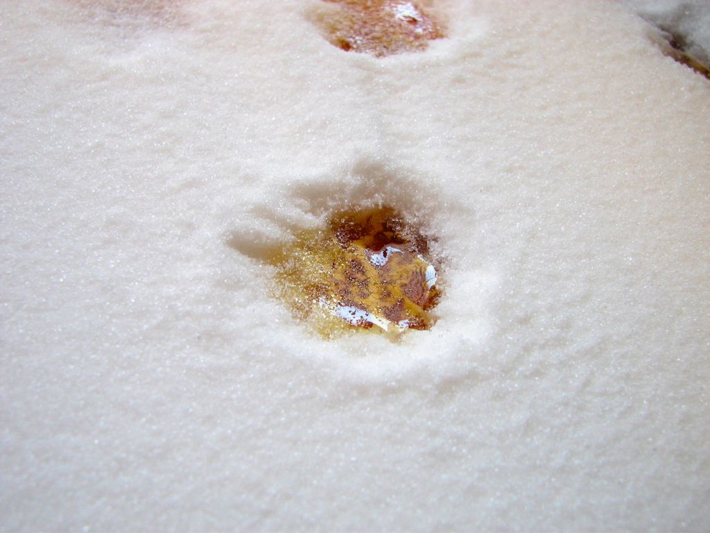
This is how a newly melted spot looks in the middle of building up a 3D object. The melted region is about 3/4 of an inch across, and has a glassy surface of amorphous sugar. The top layer is about 1/8 of an inch (3 mm) thick and is uniformly colored a light golden brown– caramelized in the melt process.
The right half of the spot appears darker because that half overlaps– and is fused to– the dot which is slightly to the side of our top dot but on the layer below. It appears darker because we are looking into a deeper layer of colored sugar. (Click through to see the image larger.)
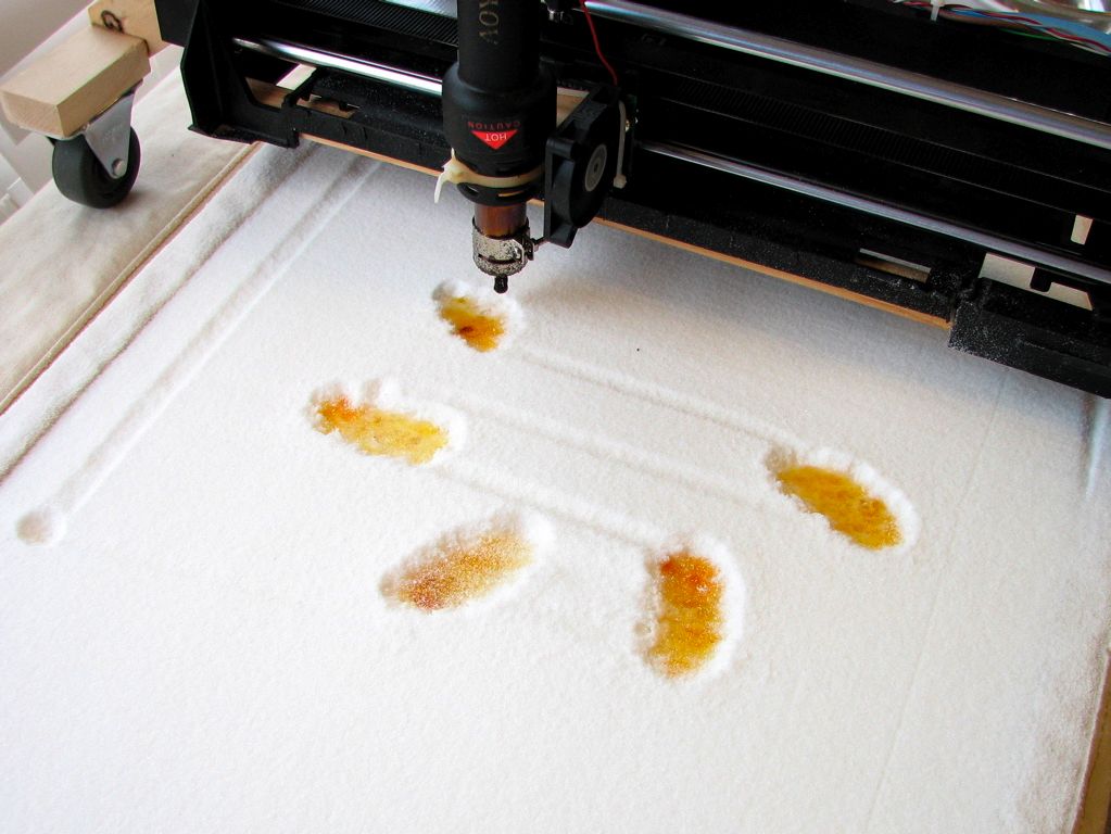
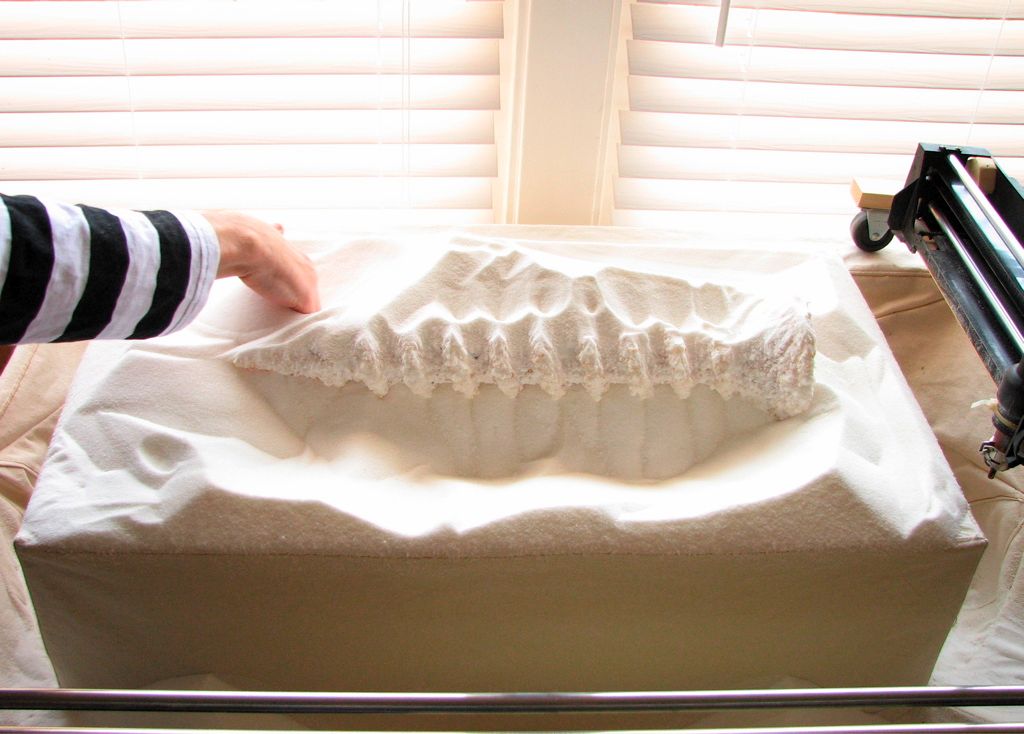
Because the hot air gun blows air continuously, it leaves a shallow trail wherever it goes. Here, you can see the trail indicate the dumb-as-a-rock toolpath of the heater over the sugar surface. Excess fusion has not been an issue so long as we move quickly between the points where we stop to melt the sugar.
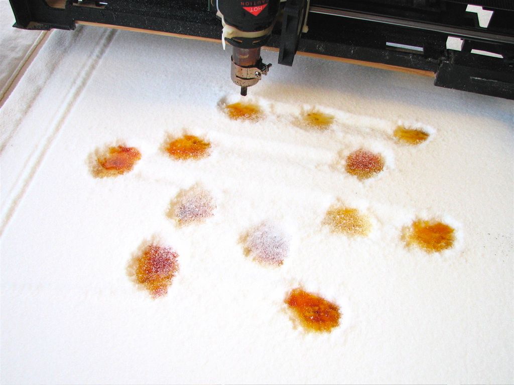
We are nearly done printing this layer, which is near the midpoint of our coil sculpture– very much like the bitmap slice that we’ve shown above. All of the spots have a glassy surface, but a few of them have been covered up by a dusting of granulated sugar.
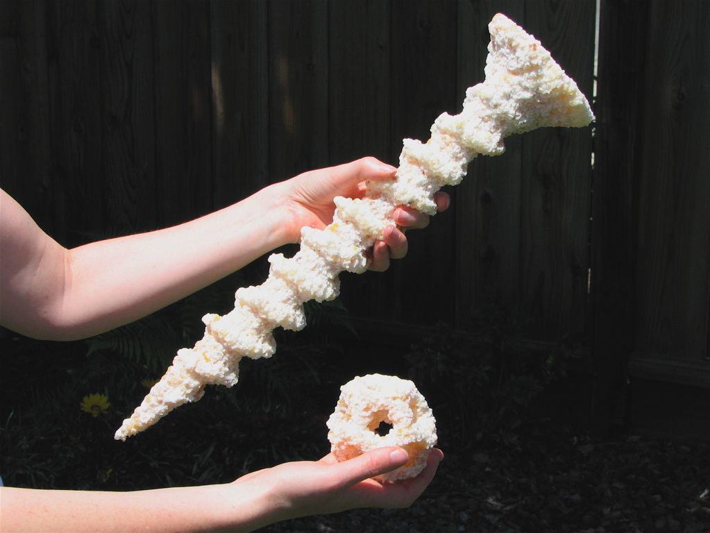
The completed toroidal coil sculpture, one of the first objects that we made with our new 3D sugar printer. We’ve hardly begun to scratch the surface of how large of an object can be made in this machine; four of these could be fabricated at once, fitting within the printable volume simultaneously.
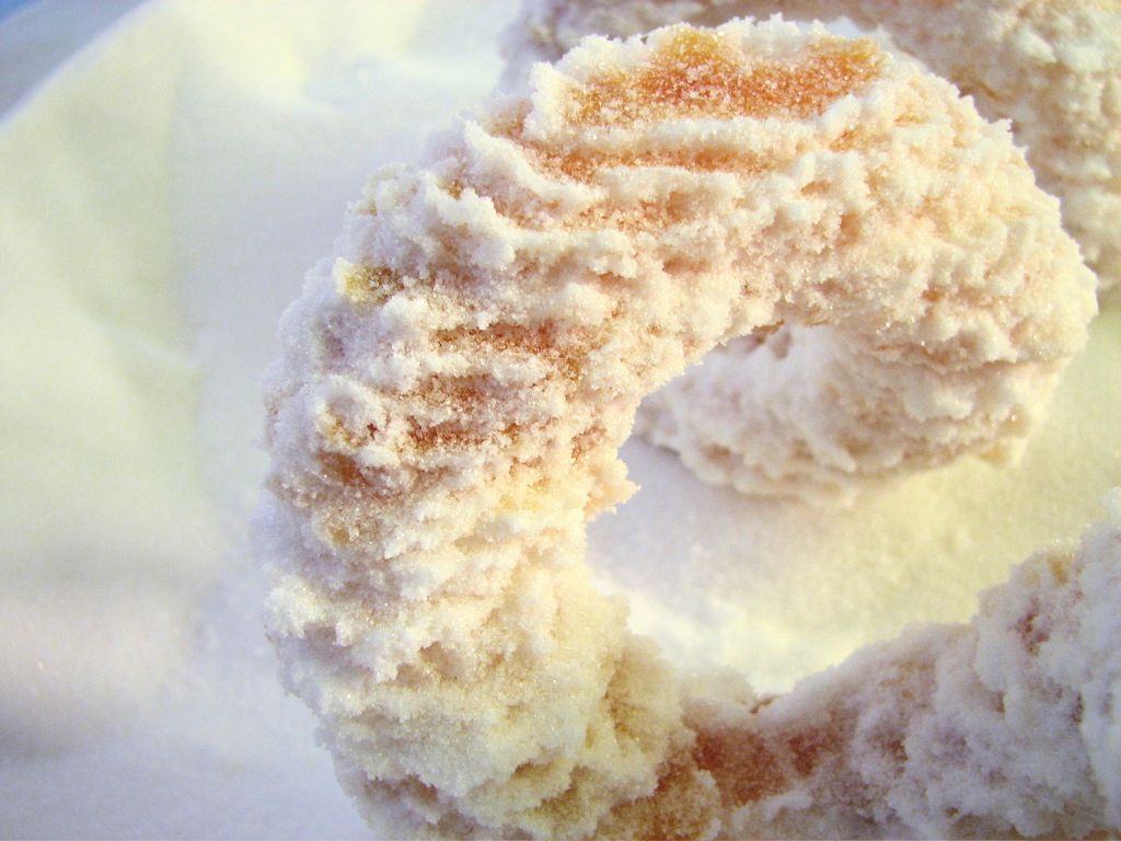
If you look at all closely, you can see the pixelated nature of our fabricated object. The bulk of the material is solid, glassy, lightly caramelized sugar. It feels and acts very much like regular glass. The outside surface is covered by loosely attached sintered sugar (white), and can be removed or smoothed over by hand.
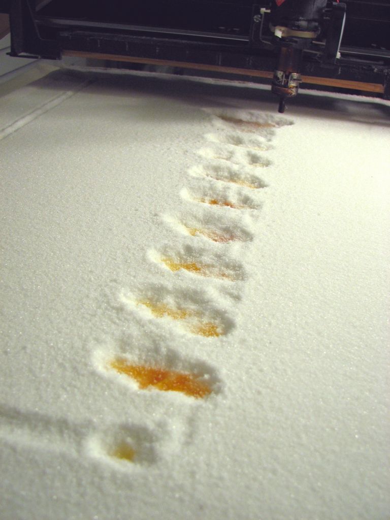
This shows the beginning of our making the model of a wood screw. This is one of the early layers, where just the edges of the threads are visible.
This layer is nearly halfway through the model of the screw. It’s a philips-head screw, so the fact that we can only see a single slot indicates that we’re not exactly at the middle yet.
Here is what it looks like after we finished printing the screw, and raised the bed of sugar up to be able to get at the model. Even after raising the piston up, some digging is still required to get the last ten pounds of sugar off the top. (This part is actually quite fun.)
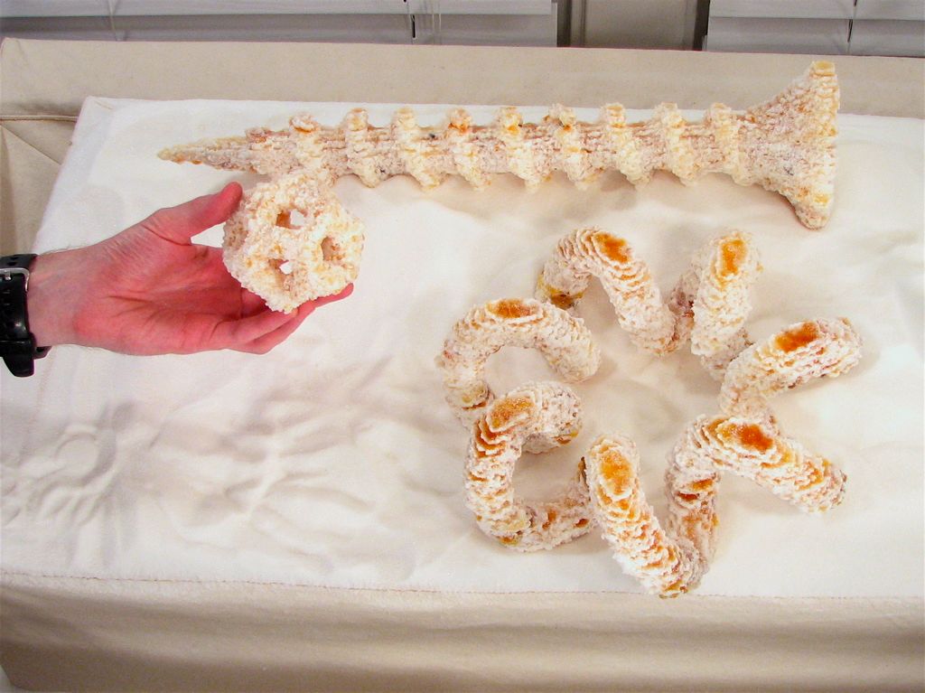
Finally, here is a group of three objects that we’ve made out of pure sugar: A little dodecahedron, the toroidal coil, and the twenty-inch-long wood screw
So how does it taste?
Like praline, no doubt.
While our process has incredible potential for making interesting food, we are still in the early stages of prototyping and we have not yet worked with the sugar under conditions that could be construed as proper food handling procedures. We are instead at this point treating the sugar as a relatively safe (but not edible) industrial chemical and prototyping medium. There is no fundamental obstacle to food-safe 3D fabrication– however we still need to carefully audit the system and make sure, for example, that the air pump for the hot air does not contain any substances that could contaminate food.
See it at the Maker Faire
Our completed fabricator will make its public debut next week at the 2007 Bay Area Maker Faire. (Our Maker Faire program entry is here.)
We will be bringing the machine itself and some of our fabricated sugar objects. We’ve decided to spend our time at the faire showing off the printer and its parts, rather than actually using it to fabricate objects. One reason is safety; we have discovered that the First Law of Laboratory Work (Hot glass looks exactly the same as cold glass) holds true for molten hot sugar as well.
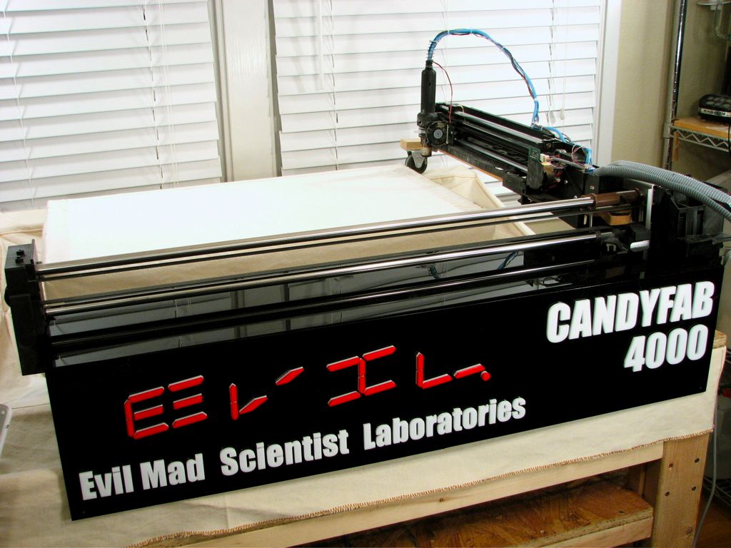
In order to make the fabricator look a little nicer for the Maker Faire, we made this combination front cover and sign that labels it the “CandyFab 4000.” Yes it’s a silly touch– but there is a certain benefit to overnaming things. (For example “Evil Mad Scientist Laboratories” sounds a lot better than “Our Kitchen.”)
We made the sign from recycled and scrap acrylic for a total cost of about $20, cutting out the letters and segments on a laser cutter before cementing them in place.
You can find more pictures of the CandyFab 4000 in this flickr photoset.
Update 7/25/2007:
We have just launched CandyFab.org. If you’re interested in designing, building, operating, or owning your own CandyFab, this is the place to start.
Unfortunately, we don’t have much free time that we can spend on fabricating objects in the week remaining before Maker Faire– Among other things, we have to prep the machine for the trip!
If we did have a few days to spend making things, I’d want to make (1) a few *giant*, stackable sugar Lego bricks, (2) an architectual model of the Parthenon, complete with removable lid, and (3) a ball-and-stick molecular model of a diamond crystal lattice. It might also be useful to try making things out of different substances, like wax and chocolate.
—
Windell H. Oskay
drwho(at)evilmadscientist.com
http://www.evilmadscientist.com/
Oh, I didn’t think you were actually going to be able to fab more things before the Faire, but just wanted to know what new projects you were going to be talking up at the event. And I suppose you will be coming home with even more cool ideas on what to make from the people you meet there.
A supermodel made of sugar, now that would be ironic.
I am visiting your site regulary, and your projects rock my sock.
Please build me one of these and sell it to me ;)
Anyway, keep up the great work.
I am sure there are many mad evil science-tools you can sugarize with this! :-)
Oh. My. God.
I love you! Please tell me when this will be on sale!
~ Cybele from Candy Blog
Wonderful! Wonderful! I love thinking about how it stacks cross-sections. Enthralling-1.
Amazing! Incredible! Stunning! Congratulations on getting it working.
The scale of it is really impressive, especially considering the cost. To improve the resolution, will you be blowing less but hotter air, or do you think it’s strictly a nozzle issue? Isn’t the Z resolution limited by how much you blow the loose sugar around?
It’s neat that you’re using POVRay to create the files. I’ve used it for engineering uses as well, similarly to what you’re doing; it’s hand to be able to take an orthogonal slice through a model and have a nice diagram at any desired resolution. I was using Perl to create the files, including the venerable Sierpinski tetrahedron, the classic spring-going-down-escalator, and Koosh balls. The last of which would be a good test of the self-supporting strength of the sugar. I can send files and scripts if desired.
Oh, and I hope you keep calling them pixels. We use the word pixel to describe 1-D ("the image is 40 pixels wide") and 2-D ("it’s a five megapixel camera"), so there’s not really any reason to use a neologism for 3-D or 4-D.
There are several issues with the heater and nozzle, and because they are all related, I have– perhaps in error– tended to lump them all together. Fundamentally, the problem is that the original design of the hot air system was to heat air that was flowing rapidly, and thus it relies upon that inflow of cool air to prevent overheating.
You have correctly identified what the solution to all of the issues is: to use hotter air at a lower velocity. Our XY resolution is limited by the size of the hot air nozzle. If we use a smaller nozzle, that increases the air velocity so much that we’re drilling a hole not melting one, and if we turn up the duty cycle of the heater, we will drive it into thermal shutdown. With some redesign, the same element could be used in a better way: What we really need is a small, thermally insulated volume– like a little oven– at high temperature with a very weak air leak that points down at the sugar.
Right now, the Z axis step size is just limited by the size of steps that we’re progrmaming. While loose media is blown about a bit by the air, it doesn’t seem to be a big problem since the effect is local and fairly uniform.
—
Windell H. Oskay
drwho(at)evilmadscientist.com
http://www.evilmadscientist.com/
I sent an email along these lines.
If your ‘hot’ spot exceeds 1500C or so, the blowing air can be dispensed with entirely – relying entirely upon the radiative energy to melt things.
The second piece of anything that hot is insulation, and Al2O3 (alumina) really rocks for this sort of thing. Both for shielding around the bulk of the hot area, and for refining the ‘beam’ of heat.
Maybe, but the design starts to get a little more tricky. The ideal heat source would be less than 1 mm across, with air velocity that of a gentle breath, and air temperature that isn’t too high above the melting point. I think that this *can* be done with the heating element that we have; it’s primarily a matter of redesigning the nozzle area with proper thermal insulation.
—
Windell H. Oskay
drwho(at)evilmadscientist.com
http://www.evilmadscientist.com/
Ideas to make your life even more complicated:
1. Add food color nozzles create stripes and or layers.
2. Add a vacuum head to facilitate the creation off hollow objects.
3. Multi media format; ex. hollow sugar rabbit with a chocolate "filling"
Ideas to make the system work "better"?
1. Add a filling system to help automate the process ( sounds like you have to add the sugar by hand at each new Z layer)
We can already do greyscale by holding the heat gun in place longer to make darker caramel at chosen locations.
It’s very easy to fabricate hollow objects: Just fab a hollow shell.
As far as filling the objects goes, that’s easily done as a post-processing operation. Alternately, adding a fused-deposition nozzle along side the heater is actually quite possible.
We’ve decided not to automate the process of adding sugar layers– it turned out to be quick, easy, and reliable by hand, so we doubt that an automated system would be worth the effort.
—
Windell H. Oskay
drwho(at)evilmadscientist.com
http://www.evilmadscientist.com/
I´ve been dealing with CNC machines the last several years and I found a combination hard to beat as far as motion control on a budget is concerned: TurboCNC (DOS based, free software, able to run on anything that has a co-processor, even an fairly old 386. I regularly use a 486 DX-100 and it works like a charm. TC can be run from a floppy disk only, depending on the size of the file) + stepping motors (taken from printers) + a cheap chopper driver (or the simplest phase drive, both easy to build). One can control up to eight axes with TurboCNC. How is that ?
Download TurboCNC from http://www.dakeng.com
I love your work !
Jorge Lourenco Jr.
What are you using to spread the sugar as each layer is added?
I’ve been thinking of a similar project, but using fine drops of water to fuse plaster, and I’m stumped for a method to add new layers of plaster, without disturbing the previously added parts.
At this point we are adding additional layers of media by hand and then smoothing the surface with a rigid straightedge.
We have a couple of ideas for hoppers and distribution methods, but have been working primarily on fusing functionality recently. It turns out that it requires very little effort to add layers by hand, and in our experience, sweeping across the top has not disturbed previous layers.
Wow… I wonder if you could make something similar on a smaller scale using Technical Lego and Mindstorms… The main limitation would seem to be creating a suitable hot air blower. Also, on a smaller scale, the raising/lowering of the base could probably be done manually.
(Tim)
Here’s one:
http://www.instructables.com/id/EVWPI8981LEP2862CL/
—
Windell H. Oskay
drwho(at)evilmadscientist.com
http://www.evilmadscientist.com/
My son and I are working on this with 2 mindstorm kits, and some motors. Using an electical heater over wax particles (hot blower with legos would be interesting…) Hope to have it in a Maker Faire here in Austin, TX this fall
Blake
If you’re going to raise and lower your bed by hand I would recommend using a ratchet system so each level is the same distance apart. By clicking through each level, as the heater finishes printing, you can get more reliable results.
I’d love to see pictures of your results with Legos. If you build plans, let me know because I would love to do something like this to build edible dishes for a dessert competition I will compete in this summer.
The vertical position is determined by a heavy-duty servo motor. A servo motor, by definition, actually measures the position of the output and controls the motor– however needed– to put the output where it is supposed to be, potentially with very high precision. In our case, it’s a linear servo motor that happens to use the motor from a car jack, and we measure the vertical position with a potentiometer. We have not yet pushed the vertical servo to the limits of its precision, and there is no reason to believe that any sort of mechanical ratchet is necessarily a better approach.
Even if sugar is manually added, computer control of the vertical axis like we have is *very* nice– it does save a little bit of time, but more importantly it lets the computer make sure that the horizontal pattern that it is drawing is the *correct one* for the vertical position that the fabber is currently at. It also makes it so that we don’t have to physically reach under or inside the machine at any point– we just operate it from the top and from the computer.
That said, I am not aware of any types of mechanical ratchets that can (1) support hundreds of pounds (2) be easily adjusted between vertical points while still supporting the load fully, (3) provide nine inches of vertical travel with smaller than 0.040" resolution (4) provide a clear numeric indication of what the present position number is, and (5) cost less than $100. If you do have anything to suggest, I am all ears.
—
Windell H. Oskay
drwho(at)evilmadscientist.com
http://www.evilmadscientist.com/
How are you applying the successive layers of sugar after each level? Not by hand, is it?
I was curious about how the new layer of sugar is added after each printing round. Are you doing it by hand?
The process to add the next layer of sugar is fully manual, and needs to be done each time that a layer finishes, which can be from several minutes to several hours, depending on the amount of 2D area that is printed on a given layer.
We had originally planned to build a large hopper above the unit that would sprinkle down the correct amount of sugar and then run the carriage back and forth with a squeegee to flatten it out. That’s not necessarily an easy task, so we decided to put it off until everything else was working.
As a temporary measure, we realized that we could just put in two scoops of sugar by hand after each layer and use a straight edge to flatten out the newly added sugar. This has turned out to be so easy and reliable that we simply lost interest in trying to make an automated system.
—
Windell H. Oskay
drwho(at)evilmadscientist.com
http://www.evilmadscientist.com/
The cat-litter scraper machines work pretty well. That might be a good place to start.
Dang! Anonymous 7:53 scooped me while I was trying to figure out how to post a comment!
Will you be releasing a ‘how-to’ guide for those who want to make one at home? I’d love to give it a go…
This article is actually intended as a loose how-to guide; there is a CAD drawing to download, a software dowload that shows you how to generating 2D slices of 3D models, and a number of hints on where to get some useful components on the cheap. We will continue to document this project as time goes on, addding (for example) new nozzle designs and the code for the servo motor drivers. Will there be a complete "set of plans?" No, because the design needs to be flexible enough to allow for using different types of recycled printer parts. It’s possible that we could standardize the design by putting a standard set of parts in a partial kit for this project, but thus far we haven’t decided to do that.
—
Windell H. Oskay
drwho(at)evilmadscientist.com
http://www.evilmadscientist.com/
This is wonderful.
A suggestion on your nozzle, try a welding supply store. A MAPP or Acetyline nozzle might be what you are needing. They are designed to focus and handle hot gasses, and may do a bit to bring your pixel size down. Ask the welding expert, tell him what your requirements or needs are. (You may need help choosing one, there are thousands of designs. Each for a specific use)
Thanks for an excellent suggestion!
Generally speaking, we need to redesign the whole heater/nozzle assembly into a version that (1) is inexpensive (2) is easy to make, and (3) works well with a lower total air flow. When we do so, a fine gas welding nozzle will be an excellent way to finish it off.
—
Windell H. Oskay
drwho(at)evilmadscientist.com
http://www.evilmadscientist.com/
I would recommend a harbor freight tools plastic welding tool. It includes the heating element and nozzle in a self contained small package on sale for $29.99. If it isn’t on sale wait until it goes on sale. You get to control the air flow but it is designed for low flow and high heat. Also very compact. You can buy it off their website too.
Wow. Super cool. (or hot?)
Have you experimented with different media, like for example extra fine sugar. My wife uses it when ever she makes fudge and there is a noticible texture difference between the extra fine and regular. I wonder if it would help get you smoother results.
-Tim C
We have not tried extra fine sugar, although we do have some at home. Powdered sugar might actually be even more interesting to try. Unfortunately, we need to improve the heater/nozzle design before the grain size is going to let us improve the resolution.
—
Windell H. Oskay
drwho(at)evilmadscientist.com
http://www.evilmadscientist.com/
This is amazingly cool.
Out of curiosity, exactly how sturdy is the final product?
Also, it looks to me in the pictures that there is residual left-over sugar on the edges of the object. Is that due to the melting or can it be blown off with pressurized air (or would that compromise the integrity of the object)?
The bulk material of the fused sugar is remarkably like glass but not quite as strong– the objects that we have made are fully rigid and potentially brittle. We don’t see any sagging or flexibility whatsoever. The weak points in the objects tend to occur as gaps between the layers, due to a potential failure mode of incomplete fusion between layers during fabrication.
You can imagine the strength of the material by thinking about hard candies that you know. Hard peanut brittle, hard toffee, and hard praline tend to be very difficult to break by hand, and our sugar sculptures are no different. Larger objects like our toroidal coil are bound to be somewhat fragile just because of the shape– it would be fragile if you made that shape out of glass as well.
The white sugar on the outsides of the object is typically sintered, or weakly fused, material. It is attached such that it cannot be blown off with compressed air, but rubbing by hand can remove much of it. Treating it like a fresh piece of sand-casted aluminum is probably a good procedure– we might try sanding it or flame-polishing the objects to anneal the surfaces.
—
Windell H. Oskay
drwho(at)evilmadscientist.com
http://www.evilmadscientist.com/
just two thoughts:
1. blowing some food coloring as powder or liquid from one side against the hot air stream of the hot air gun? e.g. with some cheap spray guns for each color mounted around the nozzle of the hot air.
of course it won’t work with subtractive colormixing but exporting rgb-colors to cmyk??
because of the caramelised sugar it will look all a bit yellowish.
2. did yout ever thought about the possibility to use water (or other colored liquid see 1.) prior to heating up and melting the sugar. might work faster and could giive a more transparent color of the finished work.
found your project today on http://www.povray-forum.de
great work, i like it a lot.
keep on going
siggi
If we use any water at all during the fabrication, the final model will end up much weaker. One of the great things about our models is that they are very rigid– since they are made of pure sugar glass. We found that even using a little bit of water to wipe excess sugar off of the hot nozzle ended up making the final model sticky.
If we can get higher precision control of the air, it’s possible that we could operate in a regime where the sugar is strictly sintered together– that would lead to a fully opaque, white model that would be suitable for coloring, perhaps with a tiny alcohol-based single-pixel inkjet. Coloring in a fully transparent model– caramelized or not– may not be very useful.
—
Windell H. Oskay
drwho(at)evilmadscientist.com
http://www.evilmadscientist.com/
Ok, I am not ashamed to say that I can’t figure out how to get layer pictures out of POV-Ray.
Any tips?
I can model in Solidworks and spit out pretty much any file format.
Thanks!
Chris
Use the POV-Ray file linked above for an example.
First render it normally to see the object as a 3D-looking object. Then, change the line in the file that says
#declare overview = 1to
#declare overview = 0and render it as a *movie* with the clock variable turned on, for 32 frames of animation. (The actual clock value does not matter– it just looks at the frame number.)
These steps are also documented in the POV-Ray file itself.
—
Windell H. Oskay
drwho(at)evilmadscientist.com
http://www.evilmadscientist.com/
// — torus.pov —
// define bottom and top points of your object_to_slice in POV model
#declare y_from = -1;
#declare y_to = 1;
#declare slice_thickness = 0.00001;
//-this defines a 3D form to create slices from———–
#declare object_to_slice =
torus { 2, 0.5 rotate x*10 }
//—————————————————————
#declare slicer = intersection { plane {-y, -slice_thickness/2} plane {y, slice_thickness/2} }
light_source { <0,1+y_to,0> rgb 1 parallel point_at <0,0,0> }
// notice this. It is a othographic camera. The only change is to define
// correct x and y vectors that will match the device aspect ratio (default in POV is 4/3)
camera {
orthographic
location <0,y_to+5,0> // if you change 5 to other, you will change the scaling
look_at <0,y_to+0,0> // this is a feature of othographic camera in POV-Ray
}
// This actually slices an object
intersection {
object { object_to_slice }
object { slicer translate <0,y_from+(y_to-y_from)*clock,0> }
pigment { color rgb 1 }
finish { ambient 0 diffuse 1 }
}
//– end of pov
// — torus.ini —
Input_File_Name=torus.pov
Initial_Frame = 0
Final_Frame = 250
Initial_Clock = 0
Final_Clock = 1
Antialias=true
Antialias_Threshold=0.1
Antialias_Depth=3
Sampling_Method=2
Jitter=false
Width=512
Height=384
//– end of ini
POV-ray will produce 251 frame from these images. Width and Height, should be equal size of your print in pixels, and number of frames is number of layers.
That works too, but I would suggest that intersecting with a box is usually a little more clear, and *will produce different results* (better results?) in the case where the slices are thicker.
—
Windell H. Oskay
drwho(at)evilmadscientist.com
http://www.evilmadscientist.com/
Intersecting with the box will produce the same results, if that box is enough large to contain sliced object (to clip only top and bottom, but leave sides as is). But, instead of worrying about clipping, I chose to use two infinine planes.
Thickness of slices in my code is given at the top of POV-file. On a thick slice all slantes edges will be gray, and I set thickess to some small value to get rid of those grays.
BTW, I see, antialiasing is also unnecessary.
You’ve actually chose to use *one* infinite plane, but let’s assume that you can find the two bugs that cause that problem. =)
Even if you *do* go to two infinite planes, you are still using a fundamentally different method. My slices use an intersection with a box, where the box height is equal to the total vertical extent divided by the number of slices. In a model two units high with 250 slices, each slice accounts for everything that happens in slices that are 1/125 units thick. You could say that it computes the horizontal envelope over each thickness slice.
Your sampling method *is different* since you are using an incomplete set of thin slices through the model. This periodic sampling leaves you exposed to the possibility of aliasing, which could cause a severe misrepresentation of what you’re trying to render, in extremely unusual circumstances. That’s obviously not a big problem if you’re careful, but periodic sampling is indeed a different technique.
In any case, when you do get the two slices working, they will be so close together– only 1/400 of the distance between the slices– that having two of them gives no benefit over using one. It makes more sense and renders faster (CSG can slow things down!) to use just one, like so:
#declare slicer = plane {y,0}
—
Windell H. Oskay
drwho(at)evilmadscientist.com
http://www.evilmadscientist.com/
Because of your work, so many people can work together, so many people have discover each other than you open a new world of communication between people.
as some others have asked, im still confused about how you get the layers stacked up? and does one layer connect to another, or are they still hot when they are put together??
this is probably the COOLEST project I have EVER seen.
When the first layer is started, there is a bed of granulated sugar. The heat gun locally melts the top surface of the bed in one point, melting the sugar at that point. The heat gun then moves to the next point, melting the sugar there. If this is done in a number of points in a row, it begins to fill in a line of melted sugar, see the photo above ("Here is the first step…"). The sugar only stays molten for about 15-30 seconds after the heat gun is removed from a point. If a second line of melted sugar is added next to the first, you can begin to fill in an area with a thin layer of fused sugar. Let’s suppose that you were making a cylinder– then the first layer would just be a circle. The depth of the melt layer is controlled by the temperature, air flow rate, and hold time at each pixel location.
After the first layer is finished, the bed is lowered slightly– by an amount equal to the melt depth– and a fresh layer of sugar is added to the top, such that the new top surface is at the same place where the original surface was. To make the next step in the cylinder, a new circle is drawn in the sugar on this layer. For each point in the circle, as the sugar in the top layer melts, it fuses to the corresponding point in the hardened sugar circle below. If we were to let the model cool and take it out of the machine at this point, you would have a solid thin disk, twice the thickness of the melt layer.
—
Windell H. Oskay
drwho(at)evilmadscientist.com
http://www.evilmadscientist.com/
Absolutely incredible. Bravo.
You might want to experiment with other sugars and sugar-like substances. Those with lower melting points may allow you to make items without getting the "carmelized" color. Dextrose and fructose seem pretty easy to find (try home brewery suppliers or bulk baking ingredients) and run about $1/lb in 50lb bags. Sorbitol is harder to find and more expensive, but melts at right around 100C.
One of the big advantages of sucrose is that it is extremely easy to obtain in bulk at reasonable prices. However, if other sugars are less expensive in bulk, they would certainly be worth the effort– I’ll have to take a look.
Thanks for the excellent tip about sorbitol! I had not appreciated that sorbitol had such a low melting point. That certainly has the potential to make a kid-safe 3D fabber. Since it’s more expensive and not good for people in large doses, perhaps it would be ideal for a smaller version of the CandyFab, designed to make tiny (high-res) candy sculptures.
—
Windell H. Oskay
drwho(at)evilmadscientist.com
http://www.evilmadscientist.com/
In a future demo, I suggest printing a model of the sucrose molecule.
An excellent suggestion. We were actually thinking of doing a wireframe model of a sucrose crystal— not so far off. We’re most interested in doing a diamond crystal lattice– it’s strong, or so we have heard. =)
—
Windell H. Oskay
drwho(at)evilmadscientist.com
http://www.evilmadscientist.com/
Just wanted to say that I’m featuring the sugar prototype fabricator (can I call it a prototypewriter?) in my marketing management distribution class as a demonstration of new distribution technology. Sure, I have no idea who prints and ships sugar art right now, but that’s not the point. One of these things in the lair, and you’re set to download and mass produce little sugar…sugar things I guess.
Hmmm, proto-typewriter or prototype-writer? There is definitely some room for confusion in that term! It does have some charm, though. If you decide to use it, I recommend correct hyphen placement.
People who make gingerbread houses have figured out which sugars look the best after melting. Check with a local cake and candy making store to buy sugars that will have much less of a color cast when cooled and hardened. If you are willing to spend more, you can get sugar that will look much more like glass.
This is chemically pure sugar, and it’s darkened because it is heated well past the point of caramelization. Burnt sugar is black, and nearly burnt sugar is light or dark brown– No changes to the *sugar* are going to affect that.
Instead, we need to spend less time heating certain points in order that they are only just brought to the melting point, not past that to the dark caramel stage. We should be able to leave the whole structure very light in color, probably very light yellow.
This is actually yet another issue that is due to the present heater/nozzle design. Several very obvious improvements to the heater and nozzle are going to do wonders for (1) the resolution, (2) the accuracy, (3) the color, (4) the uniformity of the color, and (5) the printing rate. We’ve had the printer operational for less than three weeks now, and we have not spent any time trying to make these upgrades yet. Instead, we’ve spent all of our time trying to make some objects (like the ones pictured above) that we can show off at Maker Faire. Patience. =)
—
Windell H. Oskay
drwho(at)evilmadscientist.com
http://www.evilmadscientist.com/
How about powdered sugar to increase resolution, and one of those new powerful lasers to keep from blowing sugar everywhere? Or heck, you don’t even need lasers, you could focus light from a cheap(ish) high-power light bulb using a lens? I realize the build difficulty will increase with each increase to the complexity and size of the "printing" mechanism, but still, might be something to look at.
Powdered sugar should work fine with this general process, but it’s potentially more messy than granulated sugar and– I haven’t tested this– it may not be possible to keep it fully contained with canvas. It will not improve the resolutoin since we haven’t (yet) implemented a heater/nozzle that allows us to even approach the resolution limit of granulated sugar. But… give us a chance, m’kay?
We have looked at using both lasers and light bulbs. Part of the problem is that sugar is *clear* and doesn’t efficienlty absorb the light energy from lasers that are visible or near visible. The other part, as noted above, is that they are expensive. I don’t know of any commercially available laser that would work well for this application that costs less than $1000. Also, the lasers that would work are seriously dangerous– we would need to design an eye-safe version, which might double the cost of the non-laser parts.
A light bulb is not a crazy idea; perhaps a 25 W small halogen light would work after focusing it onto powered sugar. If it worked well, it would melt a tiny spot, and so might be the basis of a high-resolution printer. Since printing very large objects would take so long, you probably wouldn’t want to make the print volume so big. I’m most hopeful that high-power LEDs could be used instead.
In any case, hot air is *still* a good option, particularly once we turn down the air flow to the gentle breath that it should be. 90 percent of all of our issues (resolution, accuracy, color….) are due to the air flow rate being so high, and our redesign of the nozzle will address this.
—
Windell H. Oskay
drwho(at)evilmadscientist.com
http://www.evilmadscientist.com/
Although relatively expensive, hama beads might make a pretty cool medium.
We plan to try printing in plastic, and actually are looking into bulk beads as a source of granular plastic– at least until we can find a more industrial source for smaller grains of plastic. Anybody know where to get bulk ABS granules on the cheap?
—
Windell H. Oskay
drwho(at)evilmadscientist.com
http://www.evilmadscientist.com/
I used to work for Panduit and they would purchase boxes that were 4x4x4 feet of powdered PVC. You could touch it within 30 seconds after extrusion, so I don’t think the melting point is way too high but I didn’t get involved in the science. I wonder if that is what you would need?
The plastic is certainly out there… I just need to figure out how to get some. =P
PVC would probably melt nicely, but I’m concerned about the fumes– it’s one of those materials that you can’t use (e.g.) in a laser cutter because (as I understand it, IANAC) free chlorine can be released.
I suspect that granular acrylic would be one of our best choices. It’s apparently a standard blasting media, like sand blasting media, but softer. It’s available in huge quantities, and quite inexpensively, less than a few dollars per pound. I haven’t been able to find a good source yet, unfortunately.
—
Windell H. Oskay
drwho(at)evilmadscientist.com
http://www.evilmadscientist.com/
Is the plastic used in laser printer cartridges available?
The housings of toner cartridges are typically made of PC-ABS, a polycarbonate/ABS copolymer. While I do suspect that injection molding media (thermoplastic resins) are a good source of raw materials, I haven’t located any suitable dealers yet.
—
Windell H. Oskay
drwho(at)evilmadscientist.com
http://www.evilmadscientist.com/
I think broomdodger meant the toner itself…
Hmmm…. That’s a possibility too… but I don’t have any idea what it would look like, melted together into a solid mass. On the bright side, it comes in full colors, and might be appropriate to use for coloring sugar… for full-color sugar printing.
—
Windell H. Oskay
drwho(at)evilmadscientist.com
http://www.evilmadscientist.com/
First of all congratulations for your project. Its great! I stumbled upon it in search for a cheap way to make sculptures I designed with a computer. I’ll surely follow your improvements and cant wait to build one myself.
As a suggestion to your software problem. I think with vvvv you can load a model, generate a cross section and calculate the xy positions for the printer and send it with udp from within a single software. and its free: http://vvvv.org. if you are not familiar I with the sofware I would offer you to patch a sample.
best regards, eno.
It looks interesting, but since it’s a closed platform, I don’t think that I could recommend it as a solution. If you do build an interface in it that might be useful for sugar printing (or a whole sugar printer), we’d certainly be interested to hear about it!
—
Windell H. Oskay
drwho(at)evilmadscientist.com
http://www.evilmadscientist.com/
there will be an interface for writing your own nodes as externals in c sharp in the near future. and the vvvv developers are always willing to help with a driver for a new interface. but what i understood of your needs, is that you just need to send udp packages to the printer. formatting these messages and timing them properly is easily possible with the existing nodes.
or is that not what you ment with "a closed platform"?
best,
eno.
It is good to have that as an additional software option for the immediate future. However, in the long term, I would like to transition the project to using entirely free (as-in-speech) open-source software toolchain.
There are a number of ways to produce the UDP packets (pd can as well), but I’m not even sure that this is the best interface to proceed with. While it is certainly convenient to use the Make Controller, it is not a particularly low-cost solution.
—
Windell H. Oskay
drwho(at)evilmadscientist.com
http://www.evilmadscientist.com/
I truly hope you guys get rich. It’s awesome, applicable, affordable… hmmm, sounds like $ well earned.
Seriously tho, hit me up if you need to give away cash.
You could make models out of the maplin Polymorph found here:
http://www.maplin.co.uk/Module.aspx?TabID=1&ModuleNo=97325&doy=27m5
This could be brought in bulk and used instead of sugar.
Looks like your link is bad, you probably meant this one. Polymorph is (we believe) a variety of polycaprolactone, a plastic that we mentioned in the article. It’s the plastic of choice for the RepRap project and you can read more about it and see other sources of it here. The chief disadvantages of it for our system are (1) that it is much more expensive than sugar– $40 for 500 g at maplin, versus $0.40 for 500 g of sugar– and (2) that the granule size is large compared to that of granulated sugar. For other properties, you can certainly argue that sugar is better or worse than plastic because it is water soluble and biodegradeable.
—
Windell H. Oskay
drwho(at)evilmadscientist.com
http://www.evilmadscientist.com/
Hey, you’re able to create some another effects with this machine, even more complex than just complex forms!
I mean the idea of fusing a sugar chain, consisting from rings that are connected only in chain-style, but not fused together. And to fuse something more complex than a simple chain. Even a doll house with a chained curtain can be fused!
Our resolution isn’t yet to the point that we’re making chain-mail curtain, but (larger) simple chains shouldn’t be difficult whatsoever.
One of the models that we’ve rendered in 3D but not printed yet is a pair of large, interlocked dodecahedra. I also think that a long but simple chain would be kind of a fun exercise. Another neat variation is a caged ball, or loose things that are trapped within a larger structure. It’s all been done in wood before, of course.
—
Windell H. Oskay
drwho(at)evilmadscientist.com
http://www.evilmadscientist.com/
Is printing in pixels/voxels the only way to go, or would it be possible to have your nozzle trace out lines and arcs in the sugar?
Right now we’re rastering the 2D images with fairly coarse (10 DPI) pixels, but we could certainly change to an arbitrary vector tool path that does not have that artificially low resolution imposed. However, at a much finer scale, even such a vector path is actually composed of pixels, since our control system is fundamentally digital.
—
Windell H. Oskay
drwho(at)evilmadscientist.com
http://www.evilmadscientist.com/
Great Project. Found it at blenderartists.org.
Well, many before me talked about powdered sugar. That would be one way. What about letting the sugar melt by only the heater-element being very close to the surface, without the air-stream? OR… do the syringe-approach from fab@home? Anyway, it’s the coolest Rapid-‘Prototyping’ machine i ever saw.
Now for the controllers: you said your linear-units are from old HP-Plotters. Why don’t you use their onboard-controller to get the motion done? You lose that much detail by preprocessing the fine Render-Geometry into pixelgraphics.
There must be a software that converts the cross-sections of a render to hpgl/2 (at least, i hope so)
(my 2 cents)
rubicon
PS: öäü (i’m german, sorry for my english)
In order for radiant heating to work, we would need to have a much larger or hotter heating element. A better option for radiant heating is to use a halogen lamp. In any case, we do think that we will be able to achive a fine, very low velocity air stream that will allow us to use much higher resolution.
The control electronics for the old HP plotters are integrated into a single, large PCB that handles all of the functions of the plotter. It’s bulky, takes its own (large) power supply, and manages a lot of functions that we don’t need (the pen changer comes to mind!). There really isn’t a way to use just a small part of the board, we’d have to keep the whole thing around. Additionally, it may not do exactly what we want, since you can imagine that it might complain (for example) that the paper isn’t loaded properly. (That type of problem is a common one that we’ve heard from other folks building machines out of old printers thad did choose to use the original electronics.) Using custom controls is our design choice, and I think that it is the right one, because it gives us complete flexibility in how the motion is executed.
Since our control system is based on the original motors with the original high-resolution quadrature position encoders, we have access to exactly the same mechanical resolution that the original motor controllers did; There would not be any benefit whatsoever to hooking up the original control board. If it were useful for us to convert the 2D slices with 1000 DPI resolution, we could certainly do so. However, since our effective resolution is much lower, it only wastes printing time to do so. There might be some benefit to moving towards a vector-printing model that could utilize more of the resolution, but thus far it has not been one of our highest priorities.
—
Windell H. Oskay
drwho(at)evilmadscientist.com
http://www.evilmadscientist.com/
You made me curious.
Today, i grabbed an old HP2500CM from the cellar and i will take it apart (no experience, yet ;) I would like to get another Printers ‘Printing’-Axis ( A quite old Star LC10 color) and only want to apply the Linefeed-Impuls to that printer’s Axis. The problem will be the mass of the whole X-Axis to move along. Well. Back to your fabulous thing:
You already lift and lower the Hot Air Nozzle, what about applying a very fine-tip soldering iron to melt the sugar?
Enough for now, leaving still impressed
rubicon
I looked inside an HP inkjet a couple of weeks ago– it had a thin transparent mylar strip that was used as the position encoder for its servo motor. Neat technology, and I wish that I could just buy that stuff by the meter. Stripping down the printers can be quite challenging and time consuming. You need to reduce the weight. But, you also need to figure out exactly which parts are important for the functions (e.g., stiffness) that you want to preserve. Take a look at our two plotters before: this became the X-axis and this became the Y-axis. You can see the two of them after cutting them down in this photo.
We do not (presently) lift and lower the hot air nozzle. We simply vary how long we spend on different spots to determine whether the sugar at a given point is fused or not. It’s a non-contact method and that has advantages. Dragging a hot element through the sugar has been suggested by a lot of people, but it has some serious drawbacks. First, sugar will stick to the tip and burn continously. It will be stinky and smoky. Secondly, it’s not clear that it would work. The hot element could catch on and drag around solidified sugar (e.g., from the layer below) unless you moved so extremely slowly that you were sure to melt anything that you touched before you dragged it. That implies that either (1) you’re moving slowly enough that perhaps the sugar will solidify in the layer that you’re already working on– more hard obstacles– or (2) the heater is hot enough to create its own set of problems. If you do try it, let us know how it goes. You might get lucky.
—
Windell H. Oskay
drwho(at)evilmadscientist.com
http://www.evilmadscientist.com/
Have you considered cane sugar, in preference to beet or other sources? When making creme brule (sp?) one needs must use cane sugar, or the caramelized topping is not crisp but leathery, it may make a difference to your art.
Crystal formation is the same for water, glass, and sugar.
If you make the room hotter so that it is warmer, but still below the melting point of sugar, each melting spot will solidify slower. The slower the sugar crystallizes the more organized the crystals are. Then it will be a lot stronger and resistant to damage. I suppose you could even sand it a bit.
Incidentally, that is also how they temper glass. They melt it and allow it to cool very slowly so that it forms a large homogenous crystal. Sometimes we buy, uh, "freezies" and put them in our -80’C freezer. They freeze so quickly that the water-sugar inside cannot form even, homogenous, or large crystals. Instead they "nucleate" to a large degree making the frozen treat very powdery or "creamsicle-ish" to eat.
That’s the principle, anyway, how you apply it? That’s up to you!
Since you are printing in a voxel/pixel format vs vectors, it seems like the easiest way to make a "faster" machine without sacrificing precision, is to parallelize. That is, modify the carriage so that it only moves 1/4 each way, and use an array of heat guns. Obviously the cost goes up, but the complexity only slightly so. You could do 16 identical but tiny peices at a time, or push one object over all 16 guns.
Speeding creation time would seem to be the deal maker for making a commercial product. Imagine making sugar sculptures for center peices for a Wedding, making 30 identical large objects would likely bring tears of boredom to the operator, but with 16 nozzles, maybe less so.
Of course, and we’ve thought of that. It’s the only obvious way to get order-of-magnitude improvement in the speed of the device. It’s a particularly important idea to keep in mind for moving towards higher resolution. As we increase the resolution, it gets harder to keep the printing time the same, let alone reduce it! The challenges, of course, are reducing the cost of the print heads down to something reasonable, and make it so we can individually activate and deactivate them quickly, without driving up the cost too much.
—
Windell H. Oskay
drwho(at)evilmadscientist.com
http://www.evilmadscientist.com/
Laser wouldn’t blow sugar around and would have much smaller heating area for finer resolution, no?
There are several reasons why we should not be using a laser, among which cost is the most important factor. This has been discussed in these comments before, and also shows up in the CandyFab FAQ.
—
Windell H. Oskay
drwho(at)evilmadscientist.com
http://www.evilmadscientist.com/
Why a laser ? Well focused regular light can generate a lot of heat too — lens + sunlight easy lights a fire. Lightbulb + parabolic mirror + lens might do the trick here.
I don’t get it.
If it’s melting the sugar on top, how exactly is it building the three-dimensional shape of it again? I can possible see the sugar melting and going to the bottom to form a possible 3D shape, but I don’t understand why one side of the shape is not completely flat.
For what I understand, rapid prototyping is about building something from the bottom up. This has the odd appearance of building from the top down. Could someone explain in more detail why it’s 3D?
Ah, I see. I found a section of the description, but part of it worries me still.
"We then lower the bed by a small amount, add a thin flat layer of media to the top of the bed,"
How do you exactly know how sugar much to add after layer is done? That’s the real question. How did you exactly do that? I suppose surface area calculation were done, right? But how would the sugar be spread out so well? That part doesn’t make sense. It would need something like a new-age carwash water sprayer to spray the new sugar over the surface to later have the new surface melted.
http://www.evilmadscientist.com/forum/viewtopic.php?showtopic=44
—
Windell H. Oskay
drwho(at)evilmadscientist.com
http://www.evilmadscientist.com/
Imagine making a pyramid.
You start by melting a rectangle then add sugar and melt a smaller rectangle then add more sugar and melt a smaller rectangle etc etc etc until you end up melting a dot. Remove un-melted sugar and you have a pyramid.
Now if you start with a dot , add more sugar and melt successively larger rectangles on top you still end up with a pyramid, but this time upside down.
Get it now ?
You guys could make a fortune selling CNC-crisped toast with an image
of Jesus on it. Just think of the hacks you could fund with that … :-)
Very cool. Have you looked at Microsoft Robotics software for controlling your motors?
No, we haven’t. It looks like it’s Windows only, and we aim to be cross-platform. We are also dedicated to making this an open source project.
Why raise the bed? Why not raise and lower the printer head?
Also, what if you put the hot air down a long thin, heavily insultated(cooled) pipe? Then you could fill the entire box with sand and just move the thin pipe around inside the sugar without having to keep adding more.
The advantage of keeping the surface of the sugar at the top of the box is that it makes adding even layers of sugar very simple – you lower the box, add the right amount of sugar, and squeegee it level with the top.
There would be many disadvantages of pushing your print head through your material. The likelihood of fusing where you don’t want material fused is high. Your print head would have to be extremely rigid and your motor very strong to push through the material. Your print head is also likely get clogged. That’s just off the top of my head – I’m sure there are more. Let’s just say that the engineering challenges would be significant.
When I first raw this over at Flicker, without an explanation, I thought it was some type of organic, exoskeleton of a coral like creature. Now the creative possibilities are endless for you and your machine. Very cool!
A new thread but, I think, a needed one.
Haven’t read it in the comments anywhere, except for the early ‘supermodel’ suggestion, though I would imagine others have thought the same, but this tech is just crying out for (hollow) huge portrait sculptures, hands or complete body sculptures and the like. Coloring would add another dimension, hey, the Greeks painted their sculpture.
interesting idea here would be to use a blu-ray burner diode as the "superheating" element, in order to get around the resolution problem. the focal spot can be as small as 0.05mm and therefore the power density can be much higher than a comparable infrared diode.
you could also use several DVD burner diodes all focussed on the same small spot from different directions to raise the temperature above the melting point.
-A
We are aware of the existence of lasers. We use them all the time, in other contexts. Please see the CandyFab FAQ for our take on the subject.
—
Windell H. Oskay
drwho(at)evilmadscientist.com
http://www.evilmadscientist.com/
Have you tried using a crème brulée torch to manually smooth out the rough edges following fabrication? It would be a hassle and require some practice, but I suspect it would make the final product look a lot better.
want to use less air and "pinpiont" your procedure, think of adding a sewing machine mechanisim and heat the needle instead (or a combination of both)?
What if you could heat all the print pins on an old Okidata print head? You would just need a scaled up version of something like that.
Try removing the arm and motor from a scanner bed. It should give you a rigid straightedge moving on a linear plane that can evenly distribute a new layer of material. by modifying it slightly you could reinforce the spreading edge and probably even add a reservoir for the material that could be filled before each new pass.
Hi,
How about this stuff.
http://shapelock.com/index.html
Yeah, it is expensive but the left over could be reused and it does deform at fairly low temperatures. You might be able to use it from a nozzle like injet tech.
Thanks,
John
I have been following the development of this project for some time now and would like to say what a brilliant project it is.
I have just started building my own, perhaps rather small, jig to fit my existing CNC machine and this is my very first attempt using a CO2 laser as the heat source and cane sugar as the fusible material. As you can see I still have a long way to go but it is just so much fun and what better way for learning can there be ?.
http://www.flickr.com/photos/tweakie-cnc/4814294653/
Tweakie.
Hi, very cool!
here in Indianapolis we have a couple of recycled building material locations, one is Habitat For Humanity Re-Store. They have all kinds of materials which vary based on donation. They also happily share a list of other such stores. One of the others has fabric – tons of it! mostly upholstery fabric,and also canvas for about $1.00 – $2.00 yd!
Re-visiting lasers… how about one of the green laser pointers? Kipkay video shows how to crank up the power http://www.youtube.com/watch?v=mcDREPlIkJY
This would greatly reduce cost of tool head, but question still remains – how well would sugar react to the light? Perhaps removing the IR filter would increase performance, at cost of vision (Do Not Look at Laser With Remaining Eye). An acrylic enclosure w/ filtering might be required – and would also help control sugar dust.
Experiment is Required. Any EMSL folks want to come to Maui to help? We have lots of locally grown/milled sugar.
LASER BEAM
I’m doing low-carb. Can you make one that works in lard? ;-)
— Shannon Love