


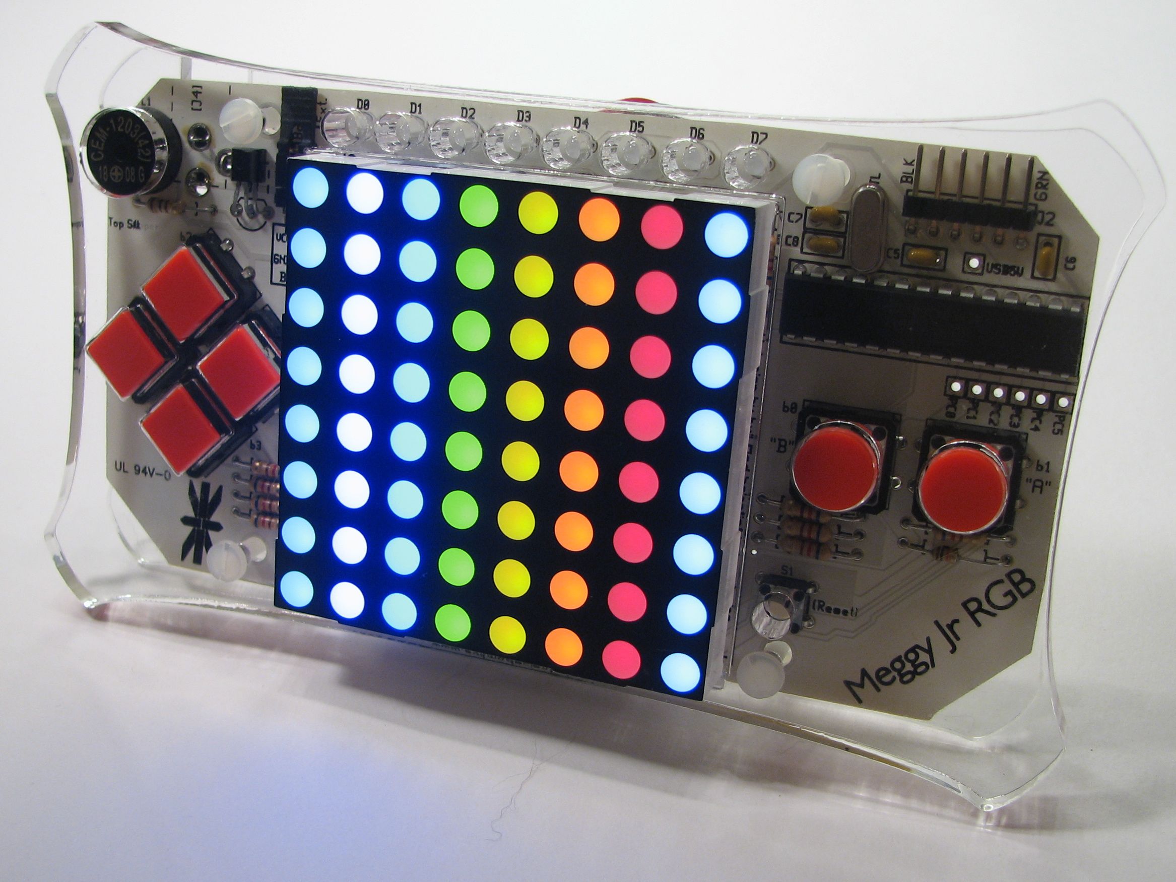
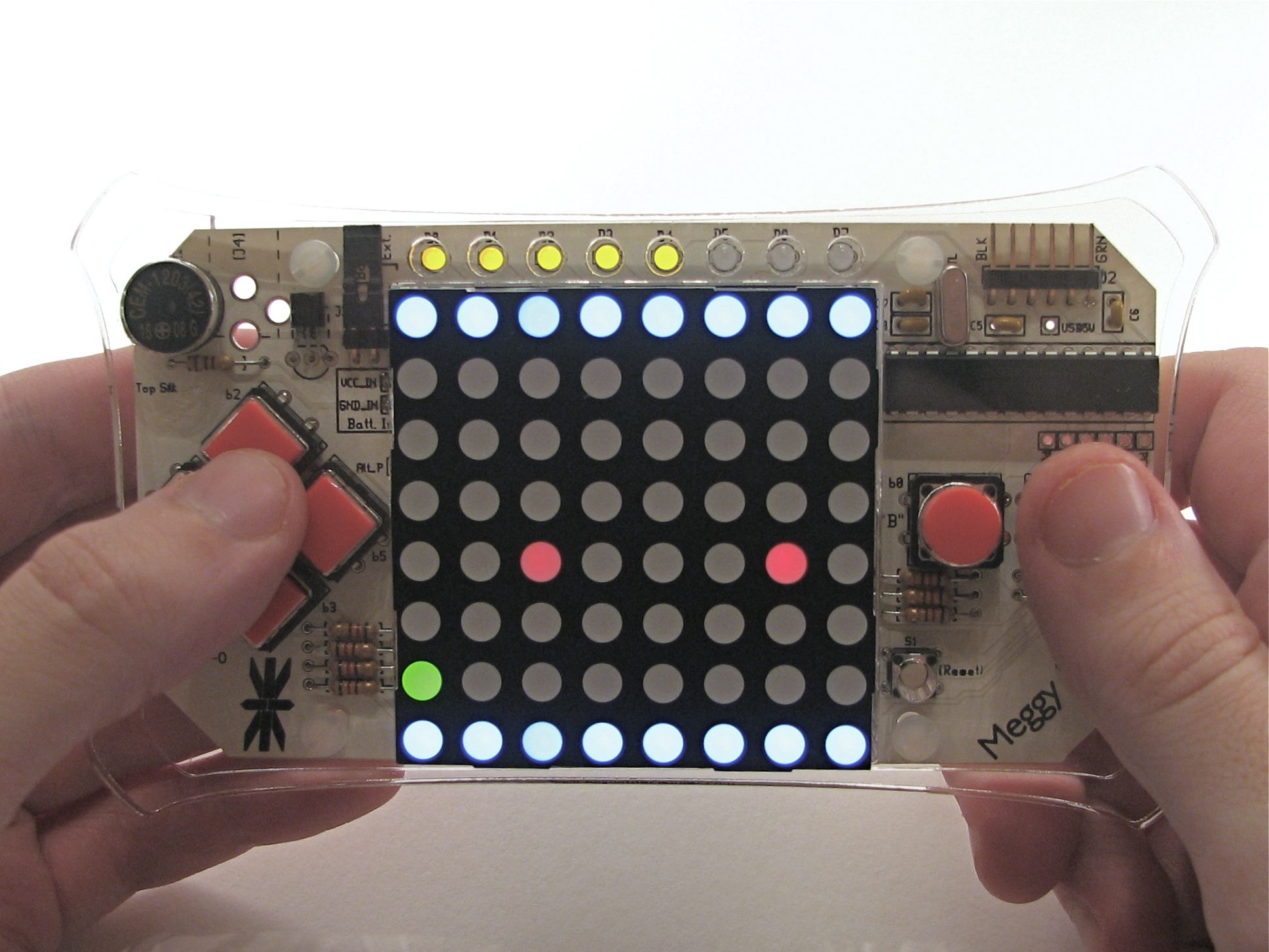
Meggy Jr RGB is a new kit that we designed as a platform to develop handheld pixel games. It’s based around a fully addressable 8×8 RGB LED matrix display, and features six big fat buttons for comfy game play. The kit is driven by an ATmega168 microcontroller, and you can write your own games or otherwise control it through the Arduino development environment. Meggy Jr is fast, programmable, open source and hackable. And fun.
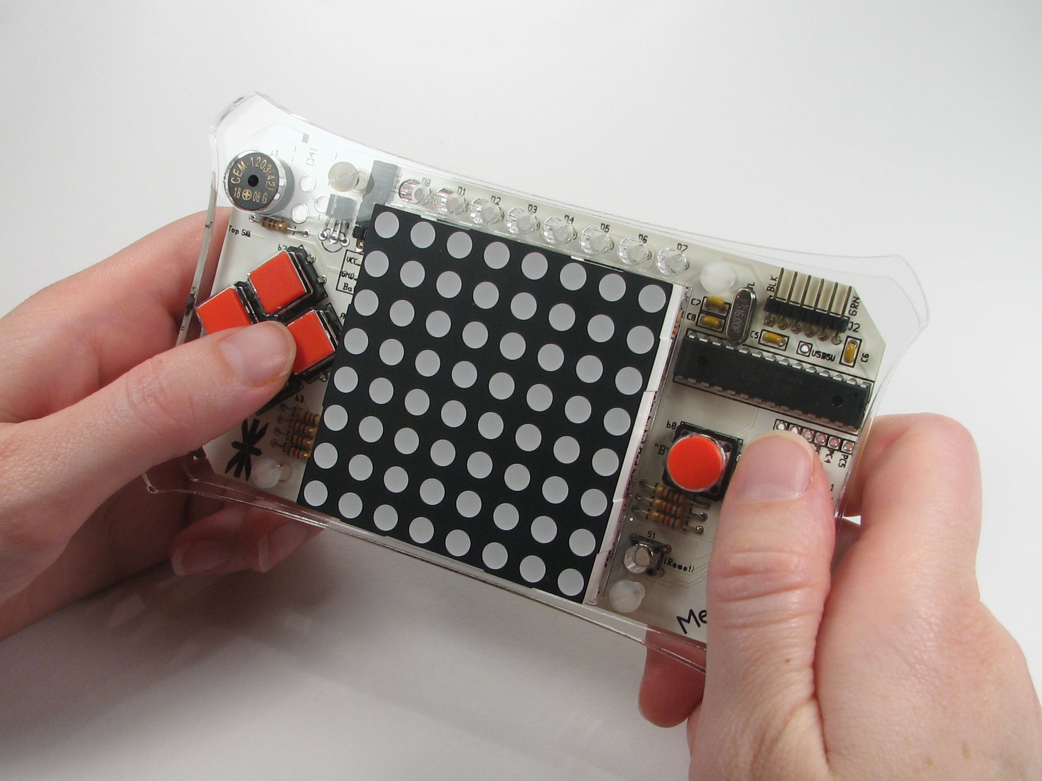
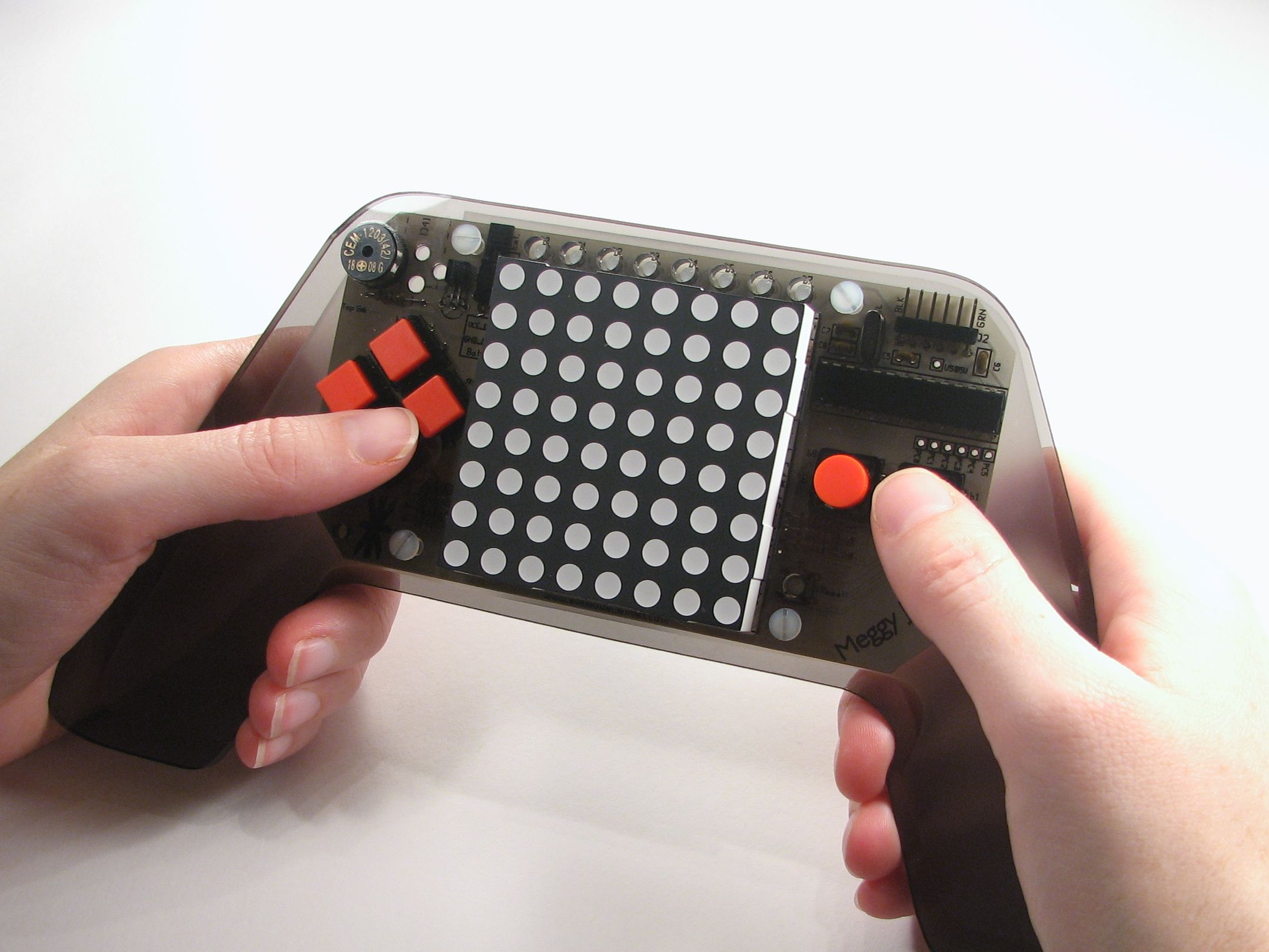
A unique feature of Meggy Jr RGB is that it is designed to be mounted inside a “handle set” — a wooden or plastic case that’s safer and more pleasant to hold than a bare circuit board. You can make, mod and customize your own handle sets to suit your taste– These are like faceplates in that you can switch whenever you want to suit your mood or the game that you’re playing, however different handle sets can radically change what the Meggy Jr looks and feels like. Above, you can see what our basic handles (left) look like, as compared to a set of custom smoke-colored batwing handles (right).
You can design your own custom handles, starting from our templates– either to make them on your own or to have them fabbed by laser shops like Ponoko or Pololu. (Ponoko in particular offers some veryinteresting materials to make cases out of, like felt and bamboo!)
You can download the two handle designs shown above as PDF and Inkscape SVG files here (780 kB .ZIP file). Each handle design consists of a sandwich of two pieces of material that go above and below the circuit board. For a perfect fit, fab the front piece (the carapace) from 0.24″ thick material (or slightly thinner), and the back piece (the plastron) from 0.12″ (or so) thick material.

Above, a sweet custom handle set for Meggy Jr: Transparent blue carapace, transparent red plastron. The possibilities are… interesting.
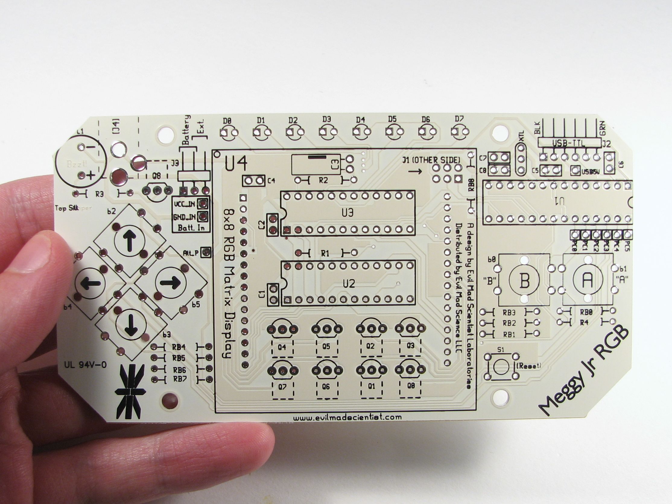
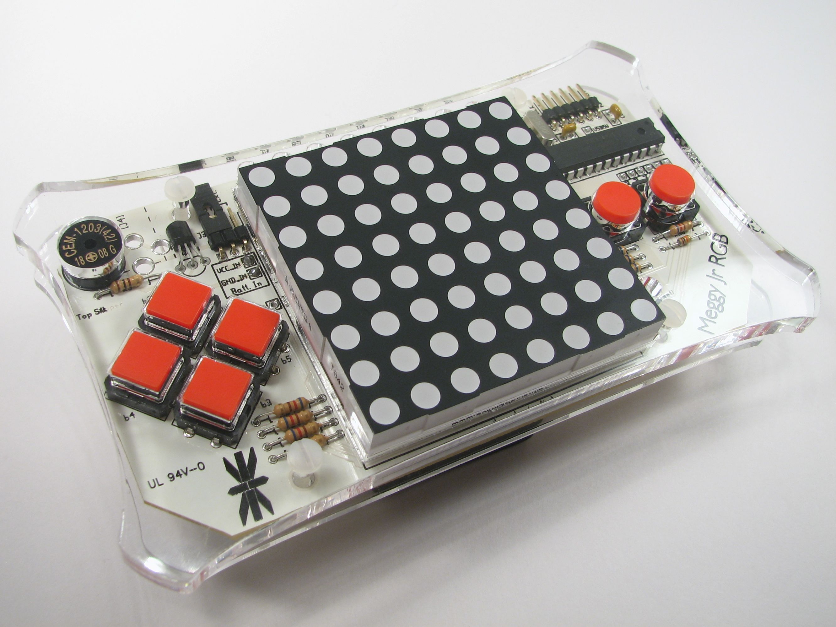
The Meggy Jr RGB printed circuit board, fabbed in white with black printing. A lot of the small components are mounted underneath the LED matrix display– it’s a big space saver. The two big chips under there are STP16DP05B1R LED driver chips. Up above the display are eight extra programmable LEDs that can be used for displaying extra data– like lives, score, ammo, or level. There’s also a little buzzer that can make appropriate bleeps buzzes and bloops, and a 16 MHz crystal oscillator.
Beyond the display, buttons, and interfaces, there are some less obvious features on the board. If you are not using the buttons at a given moment, those six inputs to the chip can be repurposed as analog or digital inputs or as digital outputs, and access points are provided. Also, the serial port TX and RX lines are not utilized while running the LED matrix, which means that they are available for turning Meggy into an ambient data device, or whatever else might come to mind. This is an open source hardware project, so you’re welcome to hack it. Start by downloading the schematic here (64 kB PDF file).
You can also download the circuit board design here (114 kB .ZIP file. The circuit board was designed in gEDA PCB— free, open-source printed circuit board software.) We are releasing the design for this board under open source licenses and under a creative commons license as well.
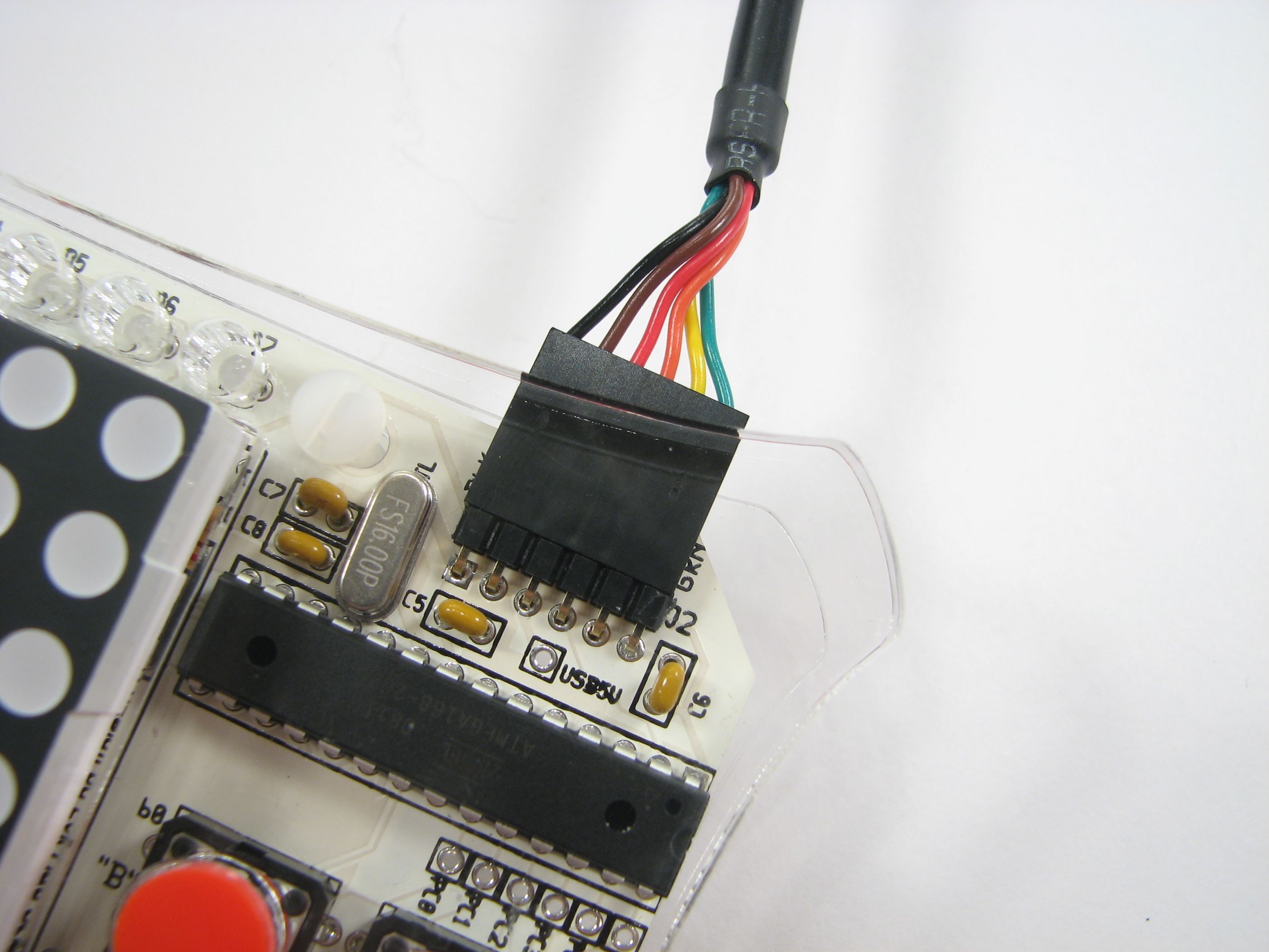
Meggy Jr RGB is designed to be programmed through the popular Arduino software environment, when you hook it up to your computer with an FTDI USB-TTL cable (shown above). This is the same programming arrangement that you’ll find on some of the popular Arduino-compatible boards such as the Boarduino and Bare Bones Boards (not to mention Peggy 2.0). And of course, Meggy Jr RGB also supports programming through a regular AVR ISP (in-system programming) connection, such as the USBtinyISP.
The first version of the Arduino library for Meggy Jr RGB has been uploaded and is now available as open source project through Google Code. This library provides fast interrupt-based screen redraw, multiple brightness levels, simple functions to write data to a video buffer, and example programs. (Additional example programs will be added soon.)
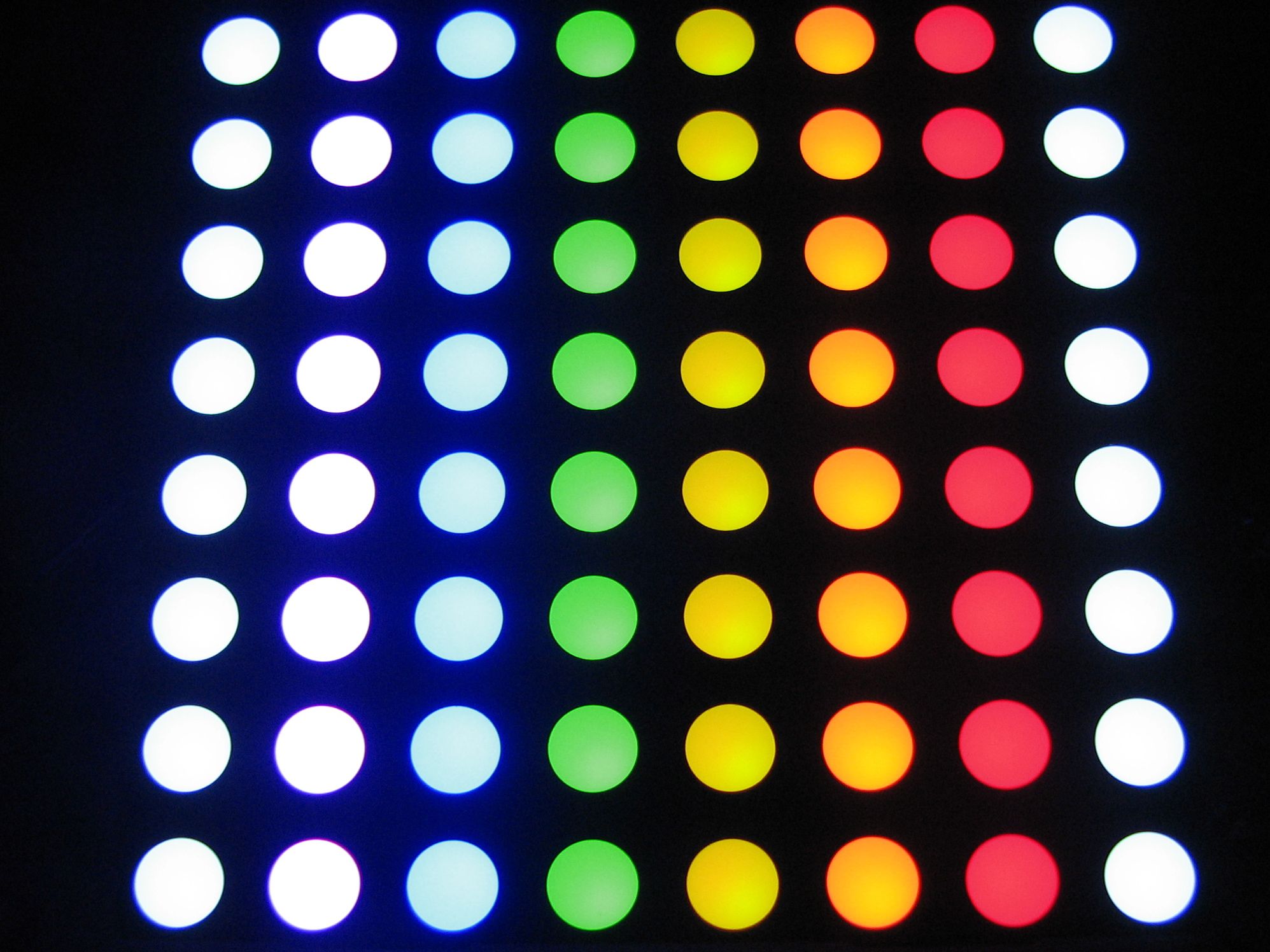

The 8×8 LED matrix is able to produce a pretty good range of colors. While it’s probably not suitable for displaying video (or true colors of any sort, really) it works extremely well for its intended purpose– displaying brightly colored pixels for games or the display of information. This would make an excellent computer-controlled status display. Or disco floor for your Lego minifigures.
Now blast those bits! Meggy Jr RGB kits are available at the Evil Mad Science Shop. If you make some interesting mods, we’d love to see pictures in the Evil Mad Science Auxiliary.
Quick Links
- Meggy Jr RGB at the Evil Mad Science Shop
- Meggy Jr RGB documentation on the Evil Mad Science Wiki
- Arduino download page. Arduino 0012 (or newer) is recommended for Meggy Jr development.
- Meggy Jr RGB Arduino Library download page.
- Meggy Jr RGB Kit build instructions. (3.9 MB PDF file. If using Acrobat to view PDF files, you may need the latest version to see all of the images.)
- Information about Programming Meggy Jr.
- How to make a Meggy Cozy.
- How to make a Meggy Link Cable.
I am completely blown away by this – you did an awesome job on this.
The laser cut handles put the whole project over the top.
Nice job!
It’s late and I am not feeling very imaginative… what games can you play with coloured dots?
Other than that, looks really really cool!!
Quite several. I made a monochrome 8×8 matrix and played quite a few fun games using a nunchuck controller, and that was before even attempting to do something with the accelerometer ;-)
Think of it as early gaming taking a more digital (rather than analog) direction. Rather than draw monochrome lines pretty much wherever you want, here you’re drawing in RGB, but on an 8×8 grid.
Thanks!
—
Windell H. Oskay
drwho(at)evilmadscientist.com
http://www.evilmadscientist.com/
The project is gorgeous, but I have to say a big thank you for the open source schematic. The STP16DP05 is exactly what I need for a system I am designing where I just couldn’t squeeze enough 40mA pins out of an AVR.
Ooh! Nice!
Accelerometer. Must. Add. Accelerometer.
:)
Ordering one today to play with. Fun!
Glad to see these for sale, they looked pretty cool at maker faire Austin. Just curious, where did the name "Meggy Jr." come from?
Our "Peggy" kits are called that because they are sort of LED pegboards– an array of locations to put LEDs. A while ago we started looking at also making similar designs, but based on monochrome LED matrix modules (rather than discrete LEDs), which can cost a little more, but improve uniformity and cut down on the amount of soldering required. So a kit like this has a similar architecture and function to the Peggy, but is a matrix not a pegboard, so the name "Meggy," (as in Peggy’s sister) seemed like a natural designation.
So… this is the first Meggy kit, and probably not the last. It’s called Meggy Jr RGB because (1) it’s small at 8×8 and (2) it’s RGB, which are distinguishing features from potential future models. :)
—
Windell H. Oskay
drwho(at)evilmadscientist.com
http://www.evilmadscientist.com/
DO WANT
Why is "B" before "A"?
It’s tradition; look at some other consoles. I’m not sure how that became the standard.
—
Windell H. Oskay
drwho(at)evilmadscientist.com
http://www.evilmadscientist.com/
This puts "A" closer to your natural hand position, right under your thumb. You have to reach a bit to get "B". Since "A" is the primary button, the layout makes perfect sense.
Just wondering playing games like Pacman, snake, pong, arkanoid or other in those 64 Led’s!!!
I can’t program yet, but i have a LOT of ideas of tiny games or apps to put inside that ATmega168!!
I hope that a WIKI would be made for this game console, it’d be very very nice…
Greetings from Spain for this project!
Nice,
I wish we had something like TechShop around here. No chance of making something like that without tools :-(
The PCB looks very clean. I’ve read you used open source tools for creating the schematic and layout. I gave the geda rpms on opensuse a try, but I can’t get the hang of it. There doesn’t seem to be a unified GUI for the whole process starting at the schematic level. I’m lost in between too many different tools.
Was there a specific tutorial you used, or did you get used to it the hard way ?
Try Eagle CAD (http://www.cadsoft.de). They have a Freeware version of their schematic and PCB layout software that I think are pretty easy to use. It’s what I use for my projects. It comes in Windows, Linux and Mac versions, too!
Eagle CAD is *NOT* free, and is *NOT* open source. It’s proprietary to all hell. How can you make open-source hardware if, when you release the designs, you need to purchase an expensive piece of software to use it? All of our open-source designs, including the Peggy series (with circuit boards up to 12×15") have design files released for free, which users can actually open and use with free software. That’s a real difference.
—
Windell H. Oskay
drwho(at)evilmadscientist.com
http://www.evilmadscientist.com/
The gEDA suite does include *too many tools* as you have found already. Making things more confusing is that the program actually called “gEDA” isn’t a necessary part of the package (or even something that I even use).
Despite all that, there *is* a good place to get started.
What you really want to do is start by making a schematic diagram and then using the wiring on that diagram as the starting place for drawing the circuit board. There is a detailed tutorial on how to go through this process, which is how *I* learned to use the gEDA tools. There’s a bit of a learning curve so you’ll have difficulty unless you actually go through the tutorial step by step and try everything that it’s asking you to. But, you can make it through, and as you can see, the results can be worth it. :)
—
Windell H. Oskay
drwho(at)evilmadscientist.com
http://www.evilmadscientist.com/
I like that you guys are using a completely open-source layout and schematic program, but couldn’t you have gone with something other than gEDA. I’m assuming your goal of going open-source is to reach as many people as possible, and therefore using a software that doesn’t have a Windows operating system version ruins the whole purpose. I know that windows users can compile their own version of it, but only very few people could do that without proper instructions. I myself do own a Linux box, and have in fact compiled gEDA for Windows, so don’t flame me as some "Stupid Windows User". I just thought that the whole point of open-source programs was to reach more people, and gEDA doesn’t do that. If you still want to stay open-source, then I’d recommend something like KiCad, which will help everyone get you look at the beauty that is Meggy Jr.
That said, amazing job on the device, and I can’t wait to get my hands on one(cant decide between batwing or normal style). Oh and where is the library for it, it was going to be released monday but I didn’t see it anywhere… Please don’t delay too long, I want to get working on an amazing game I’ve been thinking up. :)
Just a little nit-picking here: "the week of 11/17" does not mean the same thing as 11/17. The week hasn’t ended yet, so please be patient!
I’ll leave the discussion of the merits of various PCB layout programs to others.
sorry, didn’t notice that it was seek of, I guess I’m just a little to anxious for this amazing device.
All I can say is that it’s a really, really tough call what the best system is. There are *a lot* of factors to consider. At the time that we started designing open source circuits, gEDA looked actually better on the whole, after a lot of evaluation. If we were to re-evaluate now and start over, it might come out differently, but I do not see any particular program right now as compelling enough to switch. Neither gEDA nor KiCad has a monopoly on the folks doing open hardware design, and neither supports all three major OS’s without funny porting business. This will change, slowly, but for right now it’s a mess. A well-intentioned mess, but a mess none the less.
Also, the point is *not* to reach as many users as possible. (If we wanted to do that, we’d probably release the circuits in Eagle format– popular but not free.) The point is to advance the cause of open hardware design tools, and we *are* helping out by getting more people involved with every one of these projects that we release. For a lot of reasons, we won’t use something like Eagle, but mainly it’s this: how free is a design if you have to purchase an expensive piece of software to open it?
The library is coming, yes, this week. Some last minute performance tuning going on. ;)
(We aren’t sitting still– in the last couple days we have posted the complete assembly instructions for Meggy Jr RGB (a 4 MB PDF) on the store page.)
—
Windell H. Oskay
drwho(at)evilmadscientist.com
http://www.evilmadscientist.com/
Thanks for the reply, and sorry for being so snappy, didn’t mean for it to come out that way. I would never say to use Eagle, and don’t use it myself unless its absolutely necessary. Also I’m sorry for being so impatient for the code to be released, I hadn’t noticed that it was this week, and I know you’re doing your best to release it in a timely manner. Thanks again for creating this amazing and open source device, I can’t wait to begin working on it the day I get it(maybe even planning something sooner). I hope to eventually add multi-player over Bluetooth, but I’m not sure how hard that would be.
When will these start to ship? Ordered mine 11/12. Can’t wait to get started!
Meggy Jr kits started shipping Saturday the 22nd.
If you ordered on the 12th, it’s already on its way to you. :)
—
Windell H. Oskay
drwho(at)evilmadscientist.com
http://www.evilmadscientist.com/
Hello.
Looks like a nice device to me :)
Have a question: what is the construction of the LED matrix? How can 1 LED have different colours?
Thanks :)
ps: sorry if i posted comment multiple times.
Each visible LED actually has three separate LEDs in it (red, green,blue)– so the matrix actually has 8x8x3 =192 LEDs in it.
—
Windell H. Oskay
drwho(at)evilmadscientist.com
http://www.evilmadscientist.com/
oh that’s tricky :)
thanks for replying, i started to think that i missed something in semiconductors area :)
Hey! Nice Job! Especially the design of the acrylic casing looks fantastic to me. I also thought about a laser cut shell for the Mignon Game Kit. Perfect: Now we have game kits in three scales of S, M and L with Mignonette, Mignon and Meggy.
Thanks! And BTW– very nice work on Mignon 2.0!
—
Windell H. Oskay
drwho(at)evilmadscientist.com
http://www.evilmadscientist.com/
I am working on a flash based emulator for the Meggy Jr… I really hope this will help spread the word and generate a bigger audience:
http://code.google.com/p/meggy-jr-rgb-emulator/
i would love to turn this into a muscial instrument like the tenori-on
I’ve now done a bit with this device, and it’s as sweet as it looks. The library these guys have built makes creating a game almost as simple as HelloWorld.c, but still allows for low-level access of the hardware. *very* cool.
However, what I didn’t know about (until after I’d soldered the 168P to the PCB) is that there’s an upgrade to the 328P, so double the memory for not a lot more money. Sounds like a good idea to me, having written a program that is 4 bytes away from the current limits. Certainly ask for the upgrade!
-Ken
hey guys, awesome kit.
i posted a german translation of your article in my arduino wiki
http://www.freeduino.de/de/wiki/meggy-jr-rgb
I got this kit as part of the big Maker Shed sale after having my eye on it for a few months. I put it together last night, and I have to compliment you on the instructions which were very clear and helpful as well as on all the special touches. It’s a very nice kit.
I’ve been playing a lot with the TI TLC5490 chips to drive a small 4×4 matrix without multiplexing; the programming style is a bit different here, but I’m sure I can get some really cool designs going.
Now to download the library and do some programming!
Awesomely fun project, one useful tip: make sure you seat the 8 little yellow LEDs along the top really really flush with the circuit board, or the front faceplate will not seat correctly and the game buttons will stick! Maybe the tolerances for the button holes could be relaxed a bit?
>Maybe the tolerances for the button holes could be relaxed a bit?
Possibly, but the LEDs really do look *much better* when you put them in perfectly straight!
—
Windell H. Oskay
drwho(at)evilmadscientist.com
http://www.evilmadscientist.com/
hi,
can i have the circuit layout of ur game.
i am keen to make it for my own..
thnakz in advance.
my id is.
makhijaaman@yahoo.com
Links to the schematic are in the article. There’s also a link to the EMSL store, where you can buy a kit.
It looks to me like the gEDA web site has been re-organised.
The detailed tutorial mentioned above may have moved to
here.
Awwwesome !!
I just got mine and I’m completely fan of your work !
Easy to mount ( with an amazingly clear instruction book ) and easy to program !
MeggyJR should be destributed more widely, it’s completely the thing I waited for so long when I was younger !
Greetings from France !
I made a somewhat similar project (albeit with a bicolor LED array) and used a pair of 74HC595 shift registers to sink the rows. (The columns are driven by transistors; the array is common-anode.)
Problem is, the ‘595s limited me to about 6mA per LED, which, multiplexed 1/8, results in disappointing brightness in a well-lit room.
I’m planning on scaling my project up to 16×16 (four 8×8 arrays), and I’m looking for driving hardware, and I can’t find the STP16DP05B1R chip used here anywhere. Anyone know of any suitable (through-hole) alternatives?
Yes, those ‘595s are pretty good for driving LEDs through transistors, but aren’t really suitable for driving LEDs directly.
There are a few other driver chips that are compatible, although availability is spotty on most in the through-hole packages. We’ve used several different ST parts plus a few from Allegro. But long term, the best bet are the generic clones of this chip, like those from Macroblock and a few other companies. These are the *workhorse* chips of LED billboards, so you’re probably better off going with those– cheaper and they’ll be around longer. I don’t know the part numbers off the top of my head, but they’re definitely out there.
Windell H. Oskay
drwho(at)evilmadscientist.com
http://www.evilmadscientist.com/
Hi,
Can we have only 1 game into the memory of the Meggy, or can we put several games in it and choose the game that we want to play?
Cheers,
Anthony
There’s no built-in facility for programming multiple games. Think of your computer as an infinitely large cartridge system: It can hold as many games as you like, and you can load them up when you like.
There is, however, nothing stopping you from making "cartridges" (so to speak) that have more than one game in them. Some of the games that people have written start out with a "selector" screen to pick between several different games or styles of game. If there are any few particular pre-written games that you want to both load at the same time, you *probably can,* provided that you’re willing to copy and paste the code and write the selector screen.
It wouldn’t be difficult for us to write a general-purpose game selector screen, but we’ve tried to err on the side of being maximally flexible– so that you can, but do not need to, have multiple games loaded at a time.
Windell H. Oskay
drwho(at)evilmadscientist.com
http://www.evilmadscientist.com/
Where did you get those rare obsolete LED drivers. why did you choose them.
They are excellent LED driver chips, available in a through-hole package, and they were neither obsolete nor rare when we chose them. There are a number of drop-in replacements available from other brands, because this particular type of chip has become a de facto standard for LED signs and displays.
Windell H. Oskay
drwho(at)evilmadscientist.com
http://www.evilmadscientist.com/
First of all, thank you for a great DIY kit. My boys (10 and 8 years) had a Meggy Jr each for Christmas, and I have had a great time assembling and soldering the Meggies together with my boys. The assembly instructions are simply excellent. I have never seen anything as good as those! Now, we are all looking forward to programming the Meggies.
I have one idea for modification of the design. There is this jumper J3 used for selecting whether to use battery or an external adaptor as power source. However, the jumper cannot be moved without tools when the handles are mounted. Also, the power jack I got delivered together with an external 5V power supply (from your Finnish reseller Paeae where I bought the Meggies) had three leads like this:
   plug
    in
  +-----+
  |     |
  |     |
  |  2  |
  |     |
  |     |3
  |     |
  +-----+
     1
The power jack has a built in switch so when no DC-plug is in the jack, pins 2 and 3 are connected. When the plug is inserted pins 2 and 3 are disconnected, and there is +5V on pin 1 and Gnd on pin 2.
Therefore, I had a look at the circuit schematics here:
http://www.evilmadscientist.com/source/MeggyJrASchematics.pdf
(I have PCB version 1.1 and I am not sure whether this schematic design corresponds to my board.)
I had a look at the power circuit at the left and thought that I could do like this:
Now, the battery pack’s red wire (+) is always connected to Vcc via the shorted pins 2 and 3 on J3. The same goes for the +-terminal of the power plug. The battery pack’s black wire, however, only reaches ground through the DC jack when no external adaptor plug is connected. As soon as a DC plug is inserted in the jack, the battery pack’s black wire (-) is disconnected from the circuit (utilizing the switch inside the power jack). Now, the circuit gets its power from the power jack.
Do you have suggestions for how I could do this differently?
Best regards,
Martin
Hi Martin,
Yes, sounds like that (or some variant on it) would work– I haven’t checked all the way through to be sure. Alternately, add a small slider switch where the header normally goes, or connected to a header and accessible from the side.
If you’d like to continue the discussion, please direct this to the Meggy Jr forum, which is a suitable place for back-and-forth discussion: http://www.evilmadscientist.com/forum/index.php?forum=14
(The comments section of the blog isn’t really conducive to discussion other than one-time comments.)
Windell H. Oskay
drwho(at)evilmadscientist.com
http://www.evilmadscientist.com/
Hi Windell,
Thank you for suggestions and pointers to the forum, which I completely overlooked. Of course the post should have gone there.
Thanks,
Martin
Wow what a great kit. Worked first time I fired it up. I love the annotated instructions. Now to program some games.