Today we are pleased to announce the release of two new soldering kits: the 555SE discrete 555 timer and the 741SE discrete op-amp.
Both of these new kits are surface mount soldering kits — our first surface mount soldering kits — and we think that you’re going to love them.

You might be familiar with our Three Fives discrete 555 timer and XL741 discrete op-amp kits. Both are easy soldering kits that let you build working transistor-scale replicas of the classic 555 timer chip and the famous µA741 op-amp. Those two are constructed with traditional through-hole soldering techniques and are styled to like “DIP” packaged (through-hole) integrated circuits.
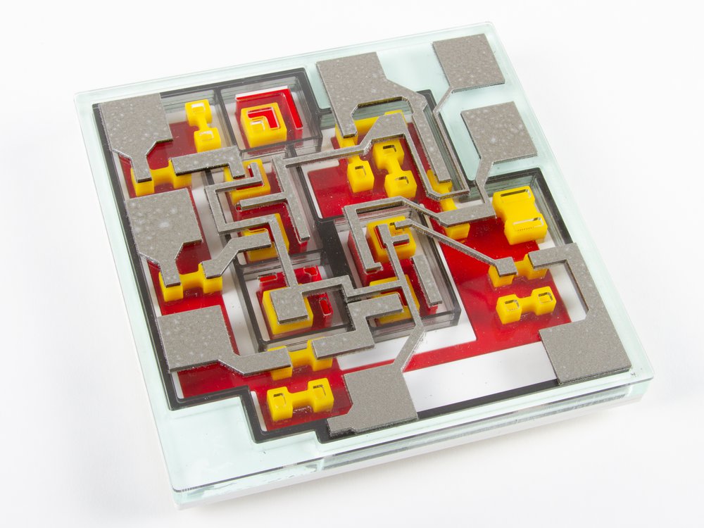
Our new 555SE and 741SE kits implement the same circuits, now with surface mount components, and are styled to look like smaller “SOIC” packaged (surface mount) integrated circuits, complete with a heavy-gauge aluminum leadframe stand. Side by side with their through-hole siblings, the new kits are exactly to scale, with half the lead pitch and a lower profile.

The 555SE and 741SE kits each come with eight (tiny) color-coded thumbscrew binding posts that you can use to hook up wires and other connections.
You can also probe anywhere that you like in these circuits — something that you generally can’t do with the integrated circuit versions.

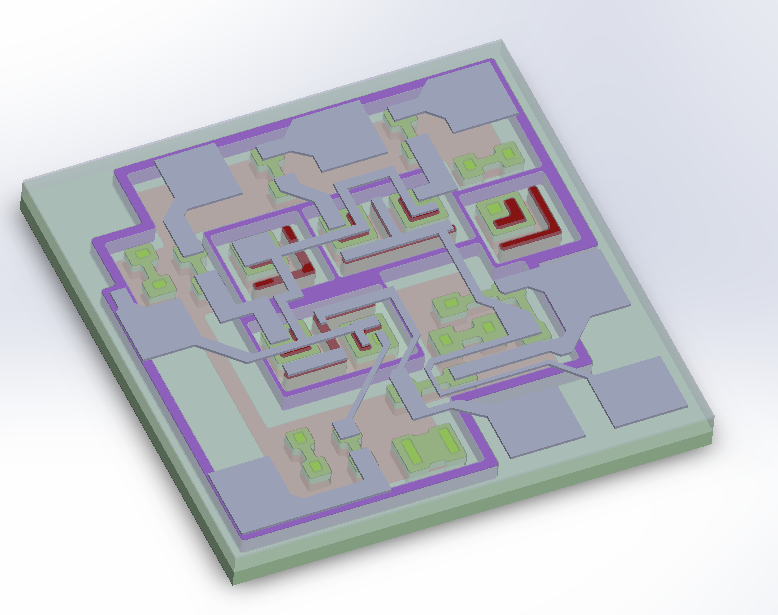
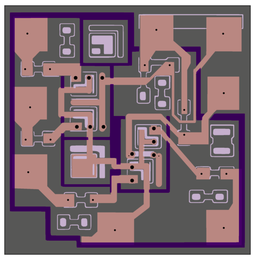
The new 555SE and 741SE circuit boards are black in color, with a gold finish and clear solder mask so that you can see the wiring traces between individual components. There are a few other neat details here and there, such as countersunk holes for mounting the board to the leadframe.
The surface mount components are relatively large, with 1206-sized resistors and SOT-23 sized transistors, and assembly is straightforward with our clear and comprehensive instructions. These kits are designed to be a joy to build, whether you’re an old hand at surface mount soldering, want some practice before tackling a project, or are introducing someone to it for the first time.

And here is the new family: XL741, the Three Fives, along with the new 741SE and 555SE.
You can find the datasheets and assembly instructions for these kits, as well as links to additional documentation, on their respective product pages.
Both new kits are part of our ongoing collaboration with Eric Schlaepfer, who we have worked with on a number of dis-integrated circuit projects including the four kits here and the MOnSter 6502.