Category Archives: EMSL Projects

Highlights of Maker Faire New York

Mayoral Proclamation of Maker Week

Maker Faire has grown to an overwhelming event, where it just isn’t possible to experience everything, but we’ve pulled together a few highlights of the 2012 “World” Maker Faire in New York.

Maker Faire started out on Friday night with a Mayoral Proclamation declaring Maker Week in New York.  Mayor Bloomberg’s words— about his own tinkering background —were surprisingly personal and resounded with many of us.

Jeri Ellsworth

Shortly after the reading of the proclamation, Jeri Ellsworth was crowned Maker Hero at the Makey Awards while decked out in LEDs from eyelashes to skirt hem. Congratulations, Jeri!

Once Maker Faire got into full swing, we only were able to catch a few heats of Nerdy Derby, but it was a huge hit.

 We also enjoyed the wooden automata by Dug North.

We had the pleasure of speaking with Alden Hart about TinyG and grblShield, two motor controller boards designed for low-cost CNC machines.

DIWire is an open source CNC wire bender from Pensa.

Another CNC project we were excited to see in person was Pancake Bot, a pancake batter dispenser made from Lego.

MFNY3

While the sheer number of 3D printers was somewhat overwhelming, a couple of newcomers stood out from the crowd: the B9Creator and the Form 1, both resin-based printers.

Felt touch sensor arms

The Touched installation by artist Rebecca Strauss would quickly retract when touched, and then gradually relax again.

arms without their felt cover

It was made with conductive felt sensors mounted over wooden armatures.

Flipbookit

The flipbookit mechanical animation kit is on kickstarter right now. It looks much better in person than on the internet.

OLED boards

These tiny OLED oscilloscopes by Gabotronics made us go “squee”!

lasercut textures

Our good friend Jenine Bressner created rich textures from laser cut fabric.

MFNY2

And forming a bridge with the makers of the past, there was a beautiful collection of patent models from The Rothschild Petersen Patent Model Museum.

Photo of Jeri Ellsworth by Becky Stern.

A Peggy 2 Word Clock

Evil Mad Word Clock

Justin Shaw of WyoLum recently presented with this little slice of awesome: One of our own Peggy 2 kits, adapted into a great big “word clock” with the help of custom software and laser-cut acrylic.

WyoLum is a small but international collective of Open Source Hardware enthusiasts who collaborate on hardware designs and other projects (like their Open Hardware Grants) that promote Open Source Hardware.   One of their great ongoing projects has been a series of open source word clocks, ClockTHREE and ClockTHREEjr, which drew inspiration from a number of sources including QlockTWO, Doug Jackson’s word clocks, and the open source design of our Peggy 2 kit.

This is, of course, one of the great things about designing Open Source Hardware: seeing unexpected uses. When we first released the Peggy 2, we didn’t even remotely consider that others would later use our circuit diagram for tips on building their own RGB word clocks.  And now it’s especially neat to see it come full circle, with the ClockTHREE software adapted to work back on the Peggy.

WyoLum’s design files for the Peggy 2 word clock are available for download here (by kind permission), and if you’re building one, you may also find helpful the ClockTHREE repository and our own documentation page for the Peggy 2.

Photo by Brian Krontz of WyoLum.

Open Hardware Summit 2012 Badges

ohs lego badge 015

The 2012 Open Hardware Summit is happening today in New York City and we had the pleasure of designing and building the badges for this year’s conference.

As you can see, the badges are built out of Lego bricks, and are a bit on the whimsical side. The hardware community’s connections to Lego run deep, as so many of us developed our mechanical understanding with it, and many of us continue to use it both for prototyping and play. (This is really only part of the badge; there is also a paper underlay below the Lego, with the attendee name and affiliation.)

We used LEGO Digital Designer, free software for Mac and Windows, to create the preliminary designs for the badges.  As we started shopping on bricklink (“the unofficial Lego marketplace”) to figure out exactly how many parts were actually available in the world in the particular shapes and colors that we needed, we gradually modified our designs to make them work with more commonly available parts.

ohs lego badge 012

We ended up running with four slightly different designs: one with plates, one with tiles, one with bricks, and one “dot matrix” with single round tiles.

ohs lego badge 014

Here is the most important part: The “modified 2×3 plate with hole” on the top, where your lanyard clips, has to be held very securely.  To be able to work with different sizes of backing plates available, we used a couple of slight variations on this theme.

Backs waiting to be finished

We ordered nearly fifteen thousand Lego bricks, sourced from twelve different suppliers, to make sure we could get all of the parts we needed.

Badges in progress

ohs lego badge 017

When all the parts finally arrived, our shop staff was happy to drop everything else they were doing to spend several days building Lego badges in time for the summit.

ohs lego badge 020

And for a final touch, we added a tool in a holder to each badge.  There are a few different tool types— our own little easter egg.

As we did with last year’s badges, we are releasing the design files (such as they are) in the preferred format for modification (lxf files). The four representative models are available for download here (37 KB zip file).

Open Hardware Summit and Maker Faire New York

Open Hardware Summit Logo

We’re very excited to be heading to New York for the sold-out Open Hardware Summit next week. There is another fantastic lineup of speakers this year, and it will be good to have the opportunity to catch up with the community after an eventful year for open source hardware.

See me at Maker Faire!After that, we’ll be going to Maker Faire New York, where you can find us demoing our kits in the Maker Shed.

We’ll be on the Make Demo Stage with the Egg-Bot on Saturday at 2:30 and Sunday at 3:00.

We hope to see you there!

Photos from the Shuttle Flyby

The crowd at NASA Ames waiting for Endeavour

This morning, we were on hand to see the Space Shuttle Endeavour make a low pass overhead, atop its Shuttle Carrier Aircraft, at NASA Ames Research Center.

As you can see in the panorama above (or at least, as you can see if you zoom in), we were deep in the crowd, out on the tarmac of Moffett Field, surrounded by the tower, Hangar One— presently stripped of its wooden exterior —and far off on the right, the two other blimp hangars.

Shuttle 009

The event organizers apparently hadn’t thought to announce it when the shuttle was getting close, and with the hangars, buildings, and crowd, we couldn’t scan the horizon either.  However, we figured out one way of telling when the shuttle was getting close: When the folks in the control tower started pointing and taking pictures.

The next thing that we saw was a pair of fighter jet escorts. And then, the main attraction:

Shuttle 008Shuttle 007

And what a view!

This modified 747 NASA Shuttle Carrier Aircraft (there are two) has tail number N905NA.  It’s been doing this for a long while— here is a photo from 1978 —but this is one of its final missions.

Shuttle 004

From here, after 25 missions into space, Endeavour moves onto retirement at the California Science Center in LA; perhaps we’ll see it again someday. But, alas, never airborne.

From the mailbag: flickering LEDs in series

We recently got a question about our flickering LEDs:

I’m wondering if it’s possible to wire these in series?

It’s a good (and not entirely uncommon) question, and the short answer is: “Yes, but not with each other.”

These LEDs have a little chip inside that turns them on and off in a flickering pattern. You can see it in the photo of the flat-topped white LED above. On the upper pad is the yellowish phosphor over the LED die. On the lower pad is the chip that turns the LED on and off.

If you put two of these in series, the first one turns the next one on and off repeatedly, interrupting the second chip and preventing it from executing its flickering pattern. The result is that you get momentary blinking, but not the nice flickering pattern.  (So yes, both would in fact light up; they just don’t behave how you might hope that they would.)

So how can you hook up a bunch of flickering LEDs together? If you want each LED to flicker separately, you can hook them up in parallel. But there is a way to use these in series with other LEDs. We can even use this to combine multiple LED colors to create some fantastic LED “flames” that would be great for stage props or putting inside pumpkins.
Continue reading From the mailbag: flickering LEDs in series

The Art Controller

Art Controller

Today we’re releasing a new open source kit: A stand-alone, microcontroller-driven relay module called the Art Controller.

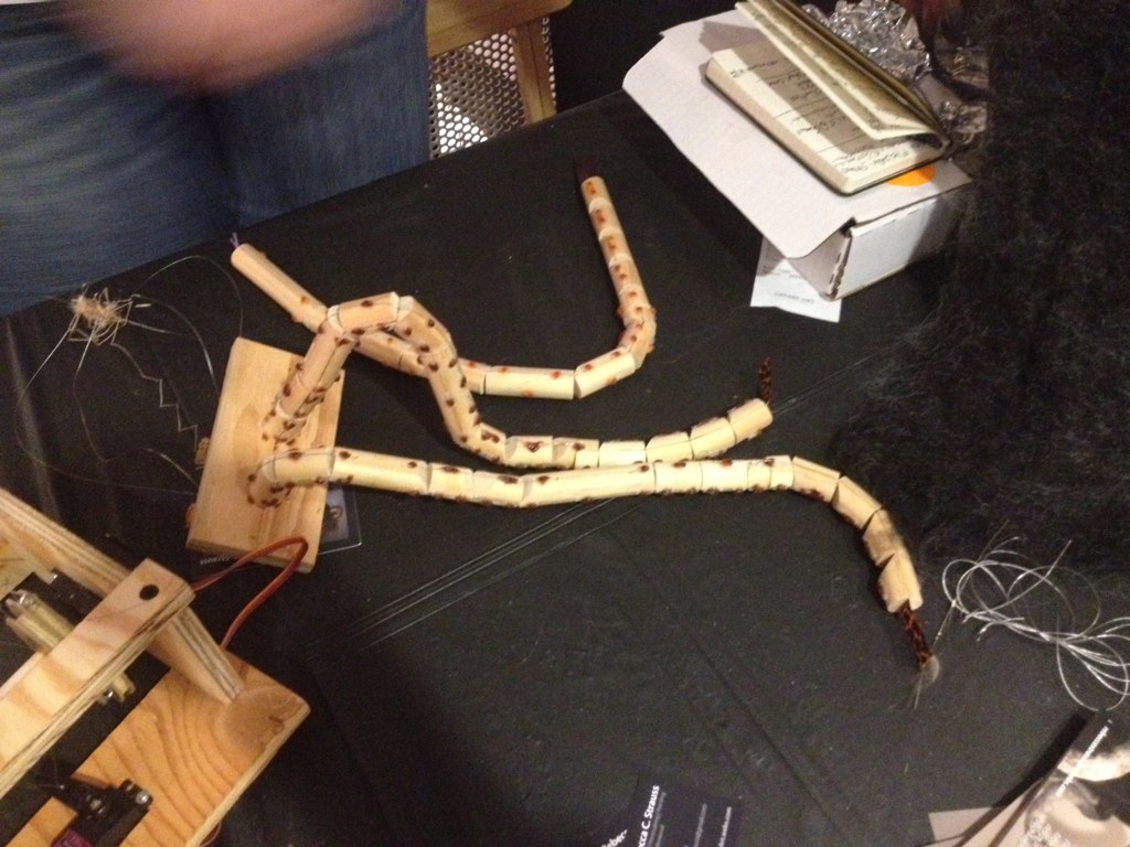
The Art Controller project was originally suggested by our friends (and Maker Faire regulars), San Francisco Bay Area kinetic artists Christopher T. Palmer and Nemo Gould.  Amongst other things that they build are amazing mechanical sculptures that need to run for a little while after a visitor presses a button or inserts a coin into the slot.

The long-established solution for driving electronic artwork (along with many similar endeavors) is to use a timer relay module; a little stand-alone board with a relay controlled by a timer.  There are several types of these: fancy programmable modules, bulletproof industrial types, and simple low-cost boards with a 555 timer and a pot that you turn to adjust the delay.  As we understand it, Christopher and Nemo go through the latter type like jellybeans.  But, what they realized that they really wanted was something just like that, except that you could reprogram it if you wanted to.

Art Controller

Hence the Art Controller.   It’s a low cost stand-alone relay module, with an on-board AVR microcontroller, an ATtiny2313, that manages the timing and I/O.

It can be used as a replacement for one of those basic 555-based relay boards, but it’s considerably more flexible in terms of timing range and functionality:

  • The timing is adjusted with an 8-position DIP switch, rather than a knob.  This cuts down on guess-and-check, but also gives a huge range. With those 8 little switches, you can select times from 1 second to 31 hours. (The ranges are 1-31 seconds, minutes, or hours, plus a few intermediate ranges.)
  • It can work as a one-shot timer or a continuously repeating timer.
  • There’s an option to trigger automatically upon turn-on (reset).
  • There’s a separate cancel input, so you can build a “STOP” button.
  • There’s an option to cancel a trigger if you push the “START” button a second time.

It comes preprogrammed, and all of those adjustments can be done with switches and wiring— handy if solder is your favorite programming language —so no computer or programming are actually required to get that far.

But, when that’s not enough, the on-board microcontroller can be reprogrammed in situ (using the board’s AVR ISP programming header) to handle the most specialized applications, potentially taking advantage of up to 16 free digital I/O pins.

And that’s pretty neat. 

Art Controller

Beyond the obvious applications in DIY projects, automation, and controlling art projects, we think that this is also going to be a fantastic relay board for education. It starts out as a (well-designed) simple function timer relay board, but can optionally transition to a full-on microcontroller development board when you’re ready for it.

So that’s the Art Controller in a nutshell: a versatile, easy to use, low-cost relay board that you can reprogram if you want to.

There’s plenty more detail on our product page: The Art Controller at Evil Mad Science.

And, special thanks to Christopher T. Palmer and Nemo Gould for a great project idea!


This post is included in our Halloween Project Archive, where you can find ideas for props, decor, and more.

Mailbag: Hacking a Mega-Peggy

grayscale

Tony writes in with a question about hacking our DIY LED matrix kits:

“I’m building a Peggy 2LE. I have completed the wiring with the exception of the LEDs. I have constructed an external frame which has 600 mounting points for my LEDs using a Matrix design of wires crossing every 3 inches. Since the Peggy 2LE has 625 LEDs I need to know how I can drive the 30 anode connections and 20 cathode connections to the wiring them to the Peggy 2. Or am I going to have to wire each LED to the PCB of the Peggy + and – LED locations?”

And, that’s actually an interesting topic.  We’ve written before (here and here) about some giant-scale variations and modifications to our Peggy 2 and Peggy 2LE LED matrix kits, but we haven’t really addressed how one might go about building it.

First off, since you asked— and though we recommend against it —it is indeed possible to build an off-board LED matrix by simply running individual running wires from every LED location on the Peggy circuit board to every LED.  There are 625 LEDs in a 25 × 25 grid, and if each has two wires… that turns out to be quite a few wires.

MakerFaire2011 - 144

While *ahem* labor intensive, this method does work. We know this partly because several people have actually done it.  The “rats nest” of thin, red-lacquered magnet wire shown above is one example, and the Peggy shown here is another victim example of this method.

Fortunately, very fortunately, there are easier ways: think 50 wires, rather than 1250. And, there are a few other clever tricks that you might want to consider when changing the size of the matrix.  For example, it’s possible to use the Peggy 2LE to drive an off-board LED matrix of size up to 25 × 32 without adding any other extra hardware.

Continue reading Mailbag: Hacking a Mega-Peggy

Basics: Picking Resistors for LEDs

5 mm warm white diffused LED

So… you just want to light up an LED. What resistor should you use?

Maybe you know the answer, or maybe everyone already assumes that you should know how to get to the answer.  And in any case, it’s a question that tends to generate more questions before you actually can get an answer: What kind of LED are you using? What power supply? Battery? Plug-in? Part of a larger circuit? Series? Parallel?

Playing with LEDs is supposed to be fun, and figuring out the answers to these questions is actually part of the fun.  There’s a simple formula that you use for figuring it out, Ohm’s Law. That formula is V = I × R, where V is the voltage, I is the current, and R is the resistance. But how do you know what numbers to plug into that formula to get out the right resistor value?

Continue reading Basics: Picking Resistors for LEDs

Build Your Own CNC Workstation Cart

CNC Workstation 1

Recently we needed a sturdy, standing-height computer workstation for our workshop. So, we designed and built one. It has turned out to be one of the most useful things that we’ve ever made. And now, we’re releasing our design, so you can build one too!

A little background: This computer station is the one that we use to operate our CNC router.  Previously, we had been operating that machine from a laptop on a rolling tool chest.  While having a tool chest handy was great, the laptop wasn’t, and the height was backache-inducingly awkward.  Once we swapped the laptop out for a desktop computer that didn’t fit on the tool chest, we needed a new solution.  We needed a new computer workstation that would actually fit the computer, be comfortable for working at standing height, be sturdy enough for use in the workshop, roll where we needed it to, and offer a decent amount of storage space for tooling and supplies.

Our workstation is CNC-cut from half-inch plywood. It is rock-solid sturdy, yet comes apart easily for transport or modifications. It features a main computer bay with an optional door, five spacious drawers that can’t fall out, enough room on top to comfortably fit a laptop (in addition to the main computer), stainless hardware, polyurethane casters, and a stiff vertical “neck” that supports a swing-arm VESA monitor mount for the main computer.

Continue reading Build Your Own CNC Workstation Cart