As the open source hardware movement matures, it’s worth taking a moment to consider the issue of version control.
Collaborative software projects make heavy use of version control– tools like Subversion and Git, and project hosting sites like SourceForge, GitHub, and Google Code –to organize and manage the contributions of many developers to a project. But as we begin to consider open source hardware, can we use these same tools and sites for effective collaboration on hardware projects?
The short answer is, “yes”– after all, people are already doing it. But the reality is that we could do much, much better. Some people think that we do need a separate “SourceForge for hardware.” That’s hard to say. But it is the case– perhaps against conventional wisdom –that existing tools can be used, today, for meaningful hardware version control.
It’s certainly possible to take any old binary file (say from a CAD program), and store it in a version control system. This is, in fact, how many of today’s open source hardware projects are managed. However, a “diff” (direct file comparison) to see what’s changed between two versions of a given file is all but meaningless.
For design files in plain-text (“ascii”) file formats, such as Inkscape‘s SVG or KiCad‘s .brd, a diff is possible and is in principle meaningful, but it is usually all but useless in practice, because CAD is a graphical sport, and we need to treat it like graphics.
An example: Suppose that you found the following snippet in the difference between two SVG files:
 <path
       sodipodi:type="arc"
       style="fill:#ff00ff;fill-opacity:1;stroke:#ffa6a6;stroke-width:0.18000001;stroke-linecap:round;stroke-linejoin:round;stroke-miterlimit:4;stroke-opacity:1;stroke-dasharray:none;stroke-dashoffset:0"
       id="path2816"
       sodipodi:cx="237.14285"
       sodipodi:cy="328.07648"
       sodipodi:rx="160"
       sodipodi:ry="84.285713"
       d="m 397.14285,328.07648 a 160,84.285713 0 1 1 -319.999997,0 160,84.285713 0 1 1 319.999997,0 z" />
You probably wouldn’t recognize that (at least not quickly) as a big magenta ellipse. While it’s perfectly legible as source code, a diff result like this would be all but useless in practice.
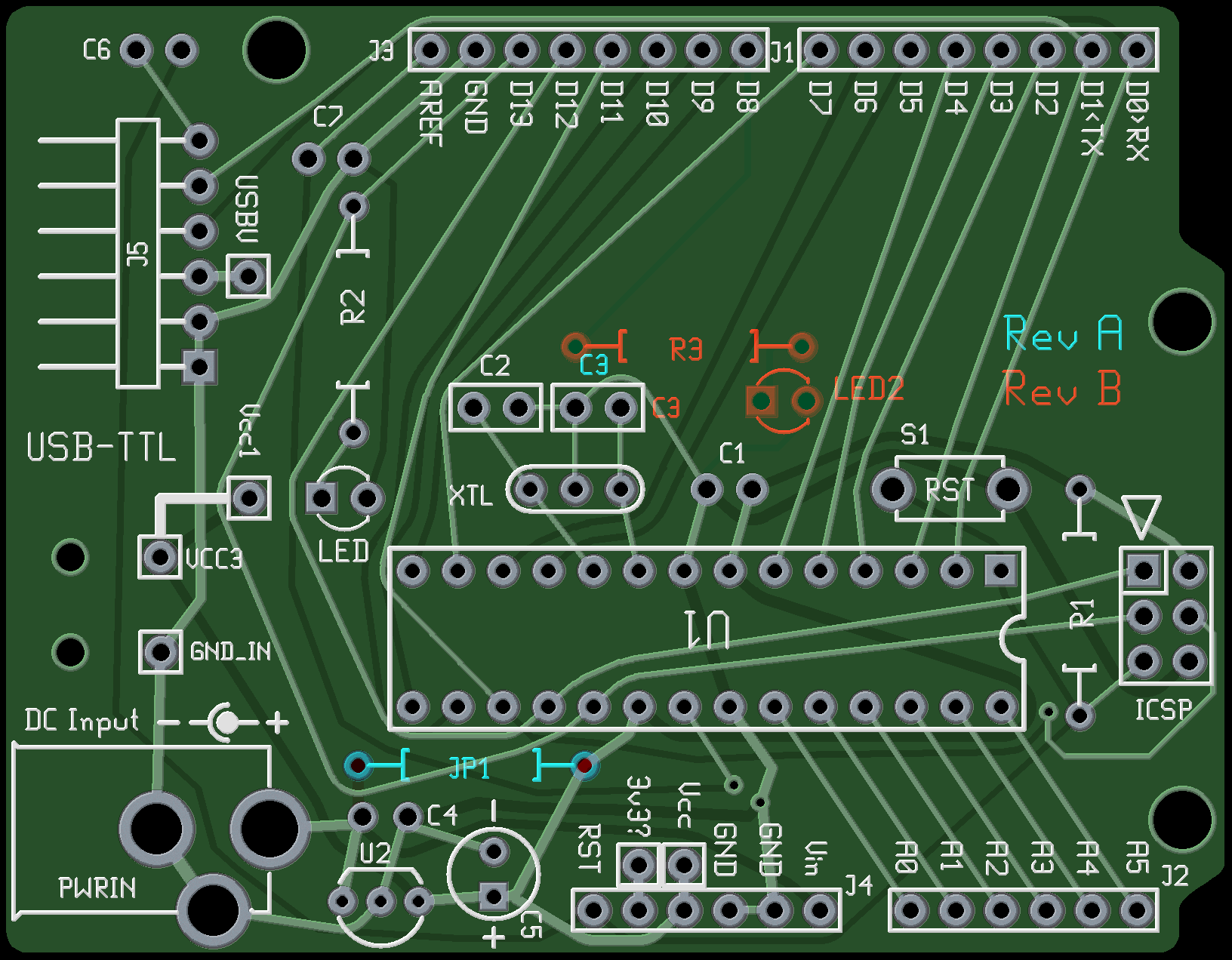
The obvious solution, is to add in some visual diffs in order to make sense of changes between design files. On the bright side, making these is remarkably straightforward, and– with a little bit of effort –practically supported by existing version control systems.
In what follows, we’ll walk through some examples of visual diffs– with bitmaps and PDF files –and discuss what you can do to help make version control work better for CAD files, and to make CAD files better for version control.
Continue reading Improving open source hardware: Visual diffs →


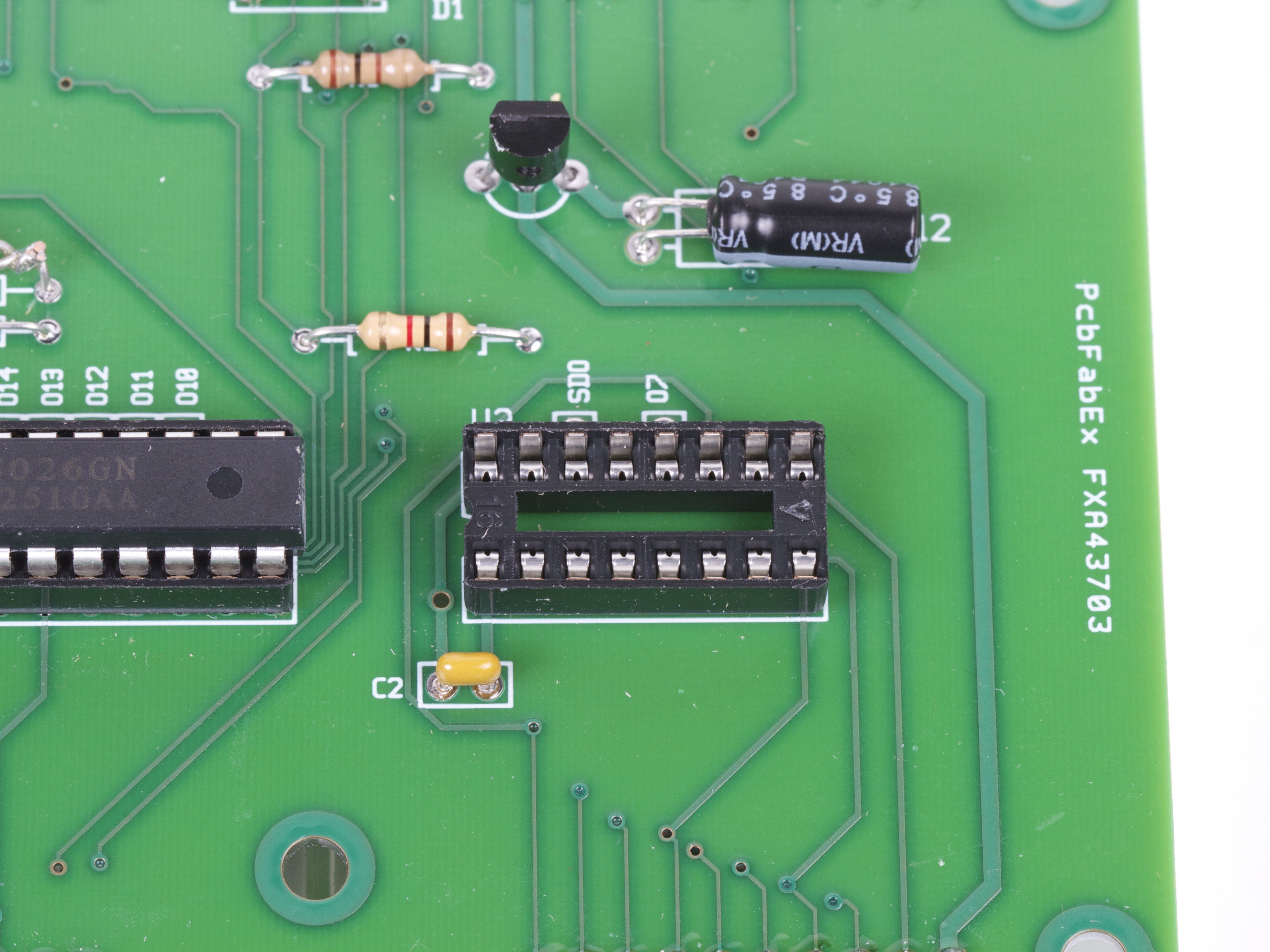
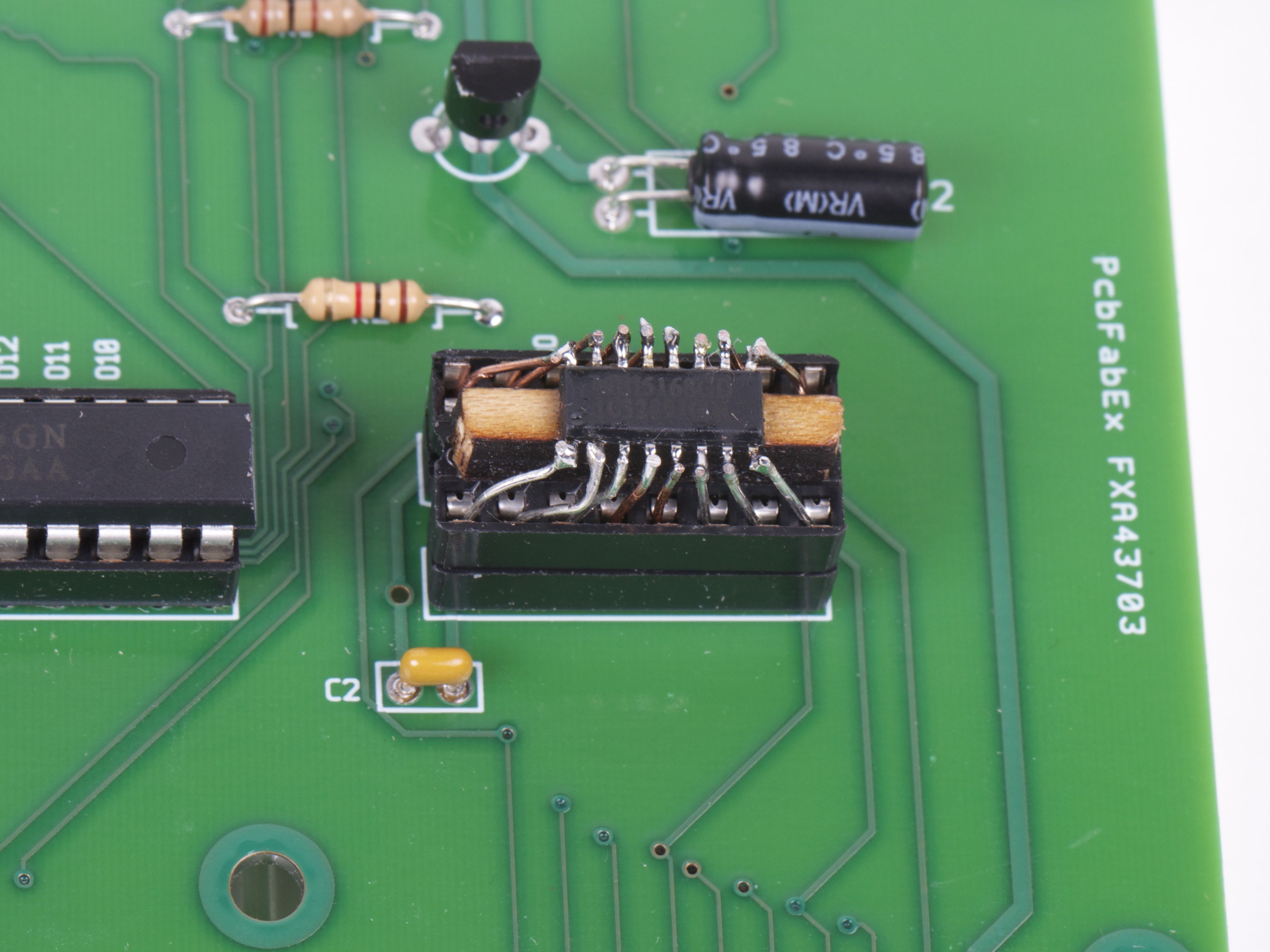
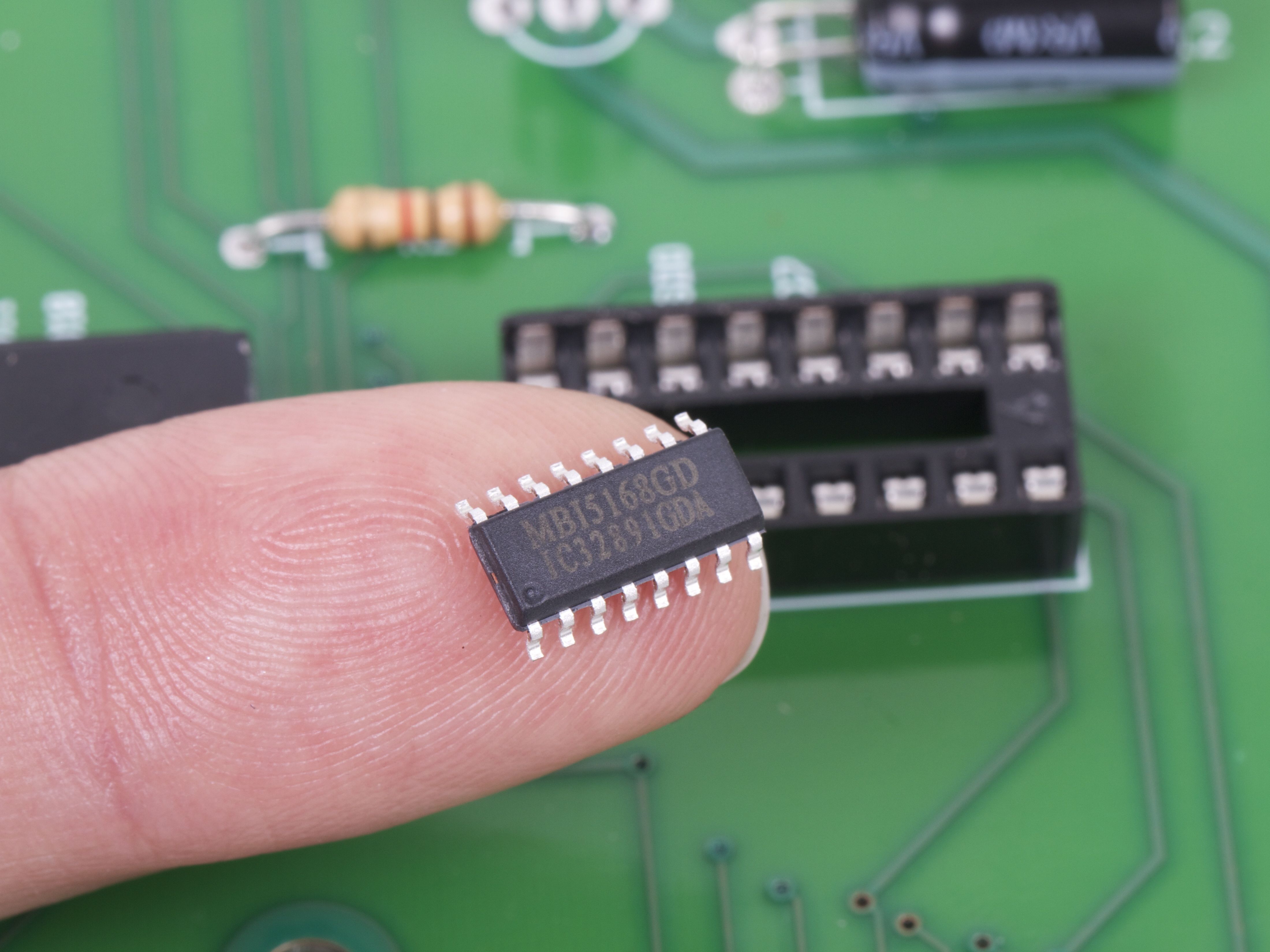 Doh! We’ve got the right chip handy, but only in the wrong package!
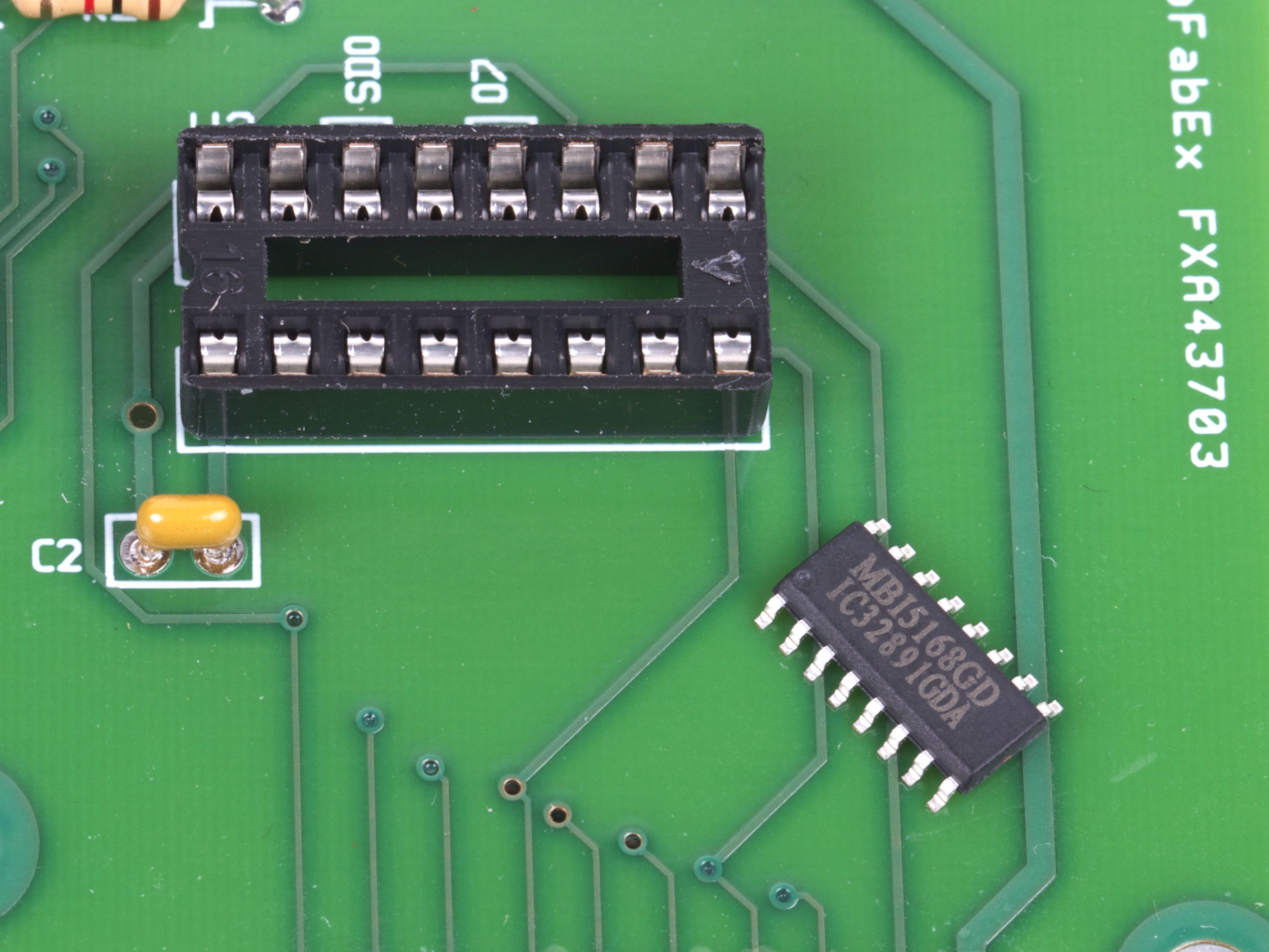 No siree, that chip will not fit in our socket. :(
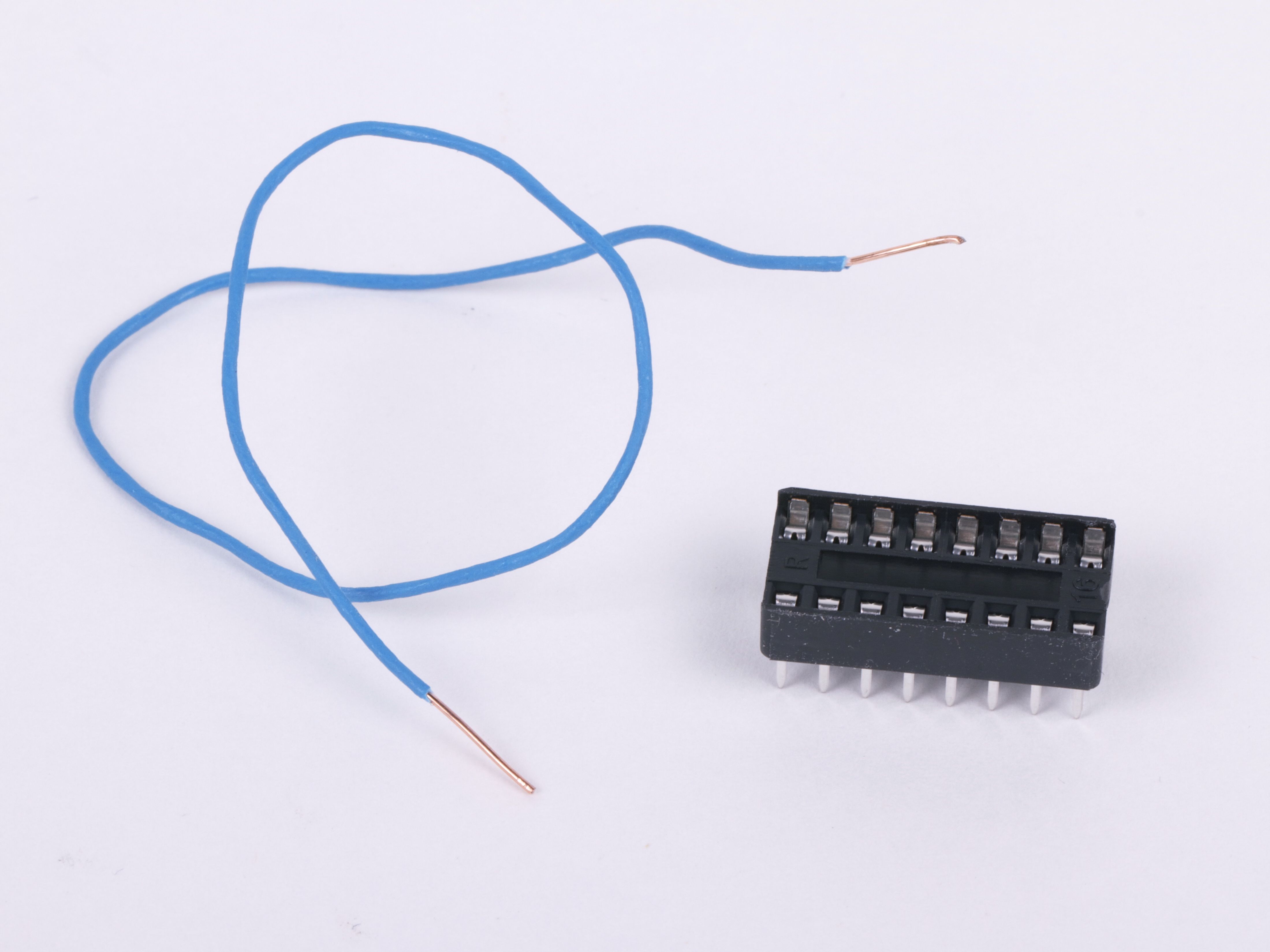 Fortunately, we’ve got tools: some thin copper wire, a spare DIP socket, and a few minutes of time. So, even without a readymade SOIC-to-DIP adapter, we’re still good to go.
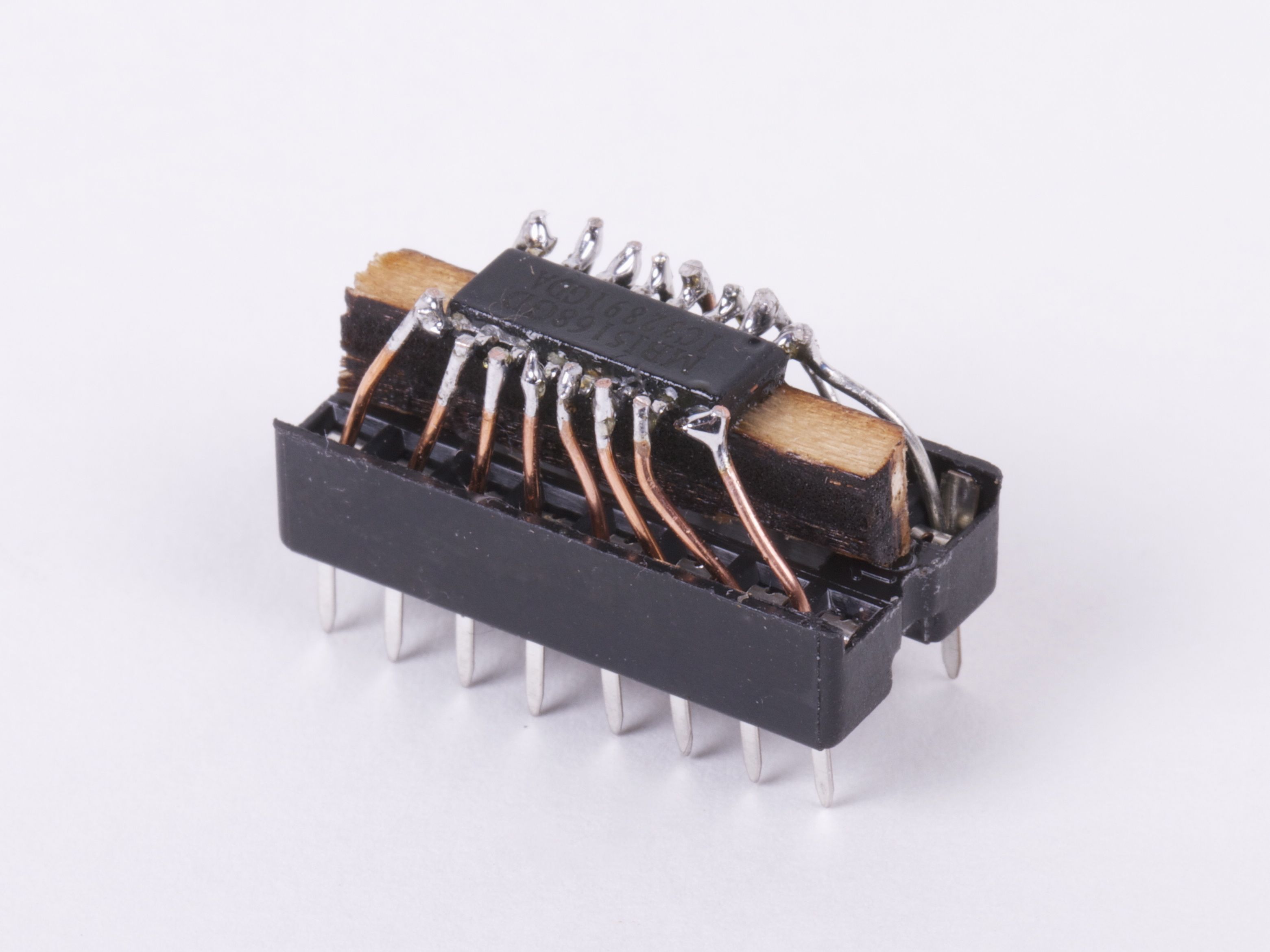 It’s helpful to raise the little chip up a bit with a wood or plastic shim, and then to fix it in place with hot or super glue. Strip the insulation off of the wire, and cut into small sections. Starting at the center of the chip, insert one end of each little wire into the socket and solder the other end to the matching pin of the IC. Trim the leads just above the chip.