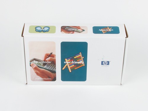
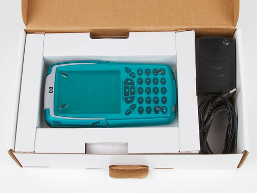
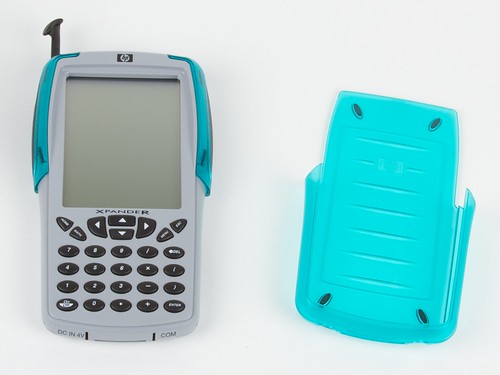
Behold, in all its glory, the “HP Xpander.”
Not just a relic from the age of brightly-colored transparent plastic, but what could have been the future of HP graphing calculators. Continue reading The HP Xpander


Behold, in all its glory, the “HP Xpander.”
Not just a relic from the age of brightly-colored transparent plastic, but what could have been the future of HP graphing calculators. Continue reading The HP Xpander
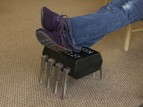
The succinct story of a modest little footstool– involving datasheets, cnc routing, laser engraving, plywood, glue, chips, all-thread, angle grinders, mountains of sawdust, dowel rods, spray paint, and a picture of a cat.
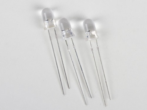

At first glance, these might appear to be normal 5 mm (“T-1 3/4”) clear lens ultrabright yellow LEDs. However, they’re actually “candle flicker” LEDs— self-flickering LEDs with a built-in flicker circuit that emulates the seemingly-random behavior of a candle flame.
In the close-up photo above, you can actually make out the glowing LED die on the left side, and a corresponding-but-not-glowing block on the right: the flicker circuit itself. In what follows, we’ll take a much closer look, and even use that little flicker chip to drive larger circuitry. Continue reading Does this LED sound funny to you?


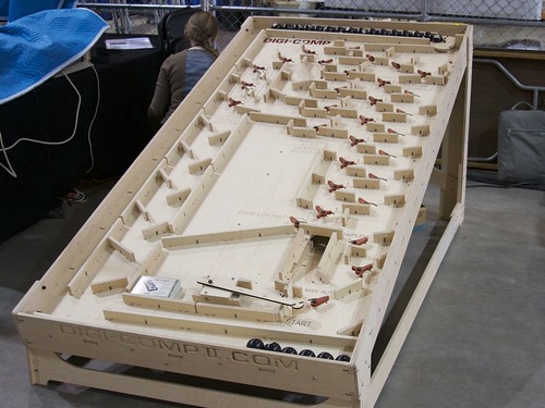
Here, you can begin to see some interesting interplay between the fast refresh cycles on the screen and the motion of the board. One might imagine that there’s still a lot of yet-unexplored potential there– with those red/green/blue/yellow/white stripes and high speed digital control, you could make almost anything.
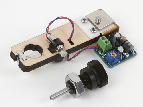
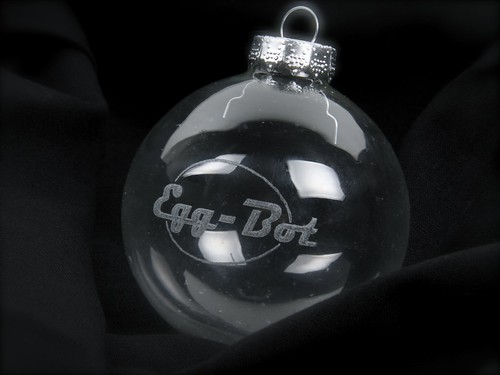
What is it? It’s a most useful little thing: a low-cost diamond engraving attachment for the Eggbot.
This turns a humble pen-plotting Eggbot into a full-on CNC-driven vibrated-tip diamond-point engraving tool, capable of light-duty marking and engraving on hard materials like glass, stone, and ceramic. Wooo!
Several weeks ago, we talked about bringing our giant Digi-Comp II to Maker Faire. But now we’re back, and we wanted to show everyone how it works– not just the many folks who came by to see it at Maker Faire.
For those of you just joining us: The Digi-Comp II is a classic 1960’s educational computer kit– an automatic binary digital mechanical computer, capable of conducting basic operations like adding, multiplying, subtracting, dividing, counting, and so forth. These operations are all conducted by the action of marbles rolling down a slope, directed by mechanical switches and flip flops that act as logic gates. Our version is a modern, larger-than life remake. A functional clone, but sized up to use billiard balls instead of small marbles. (The video is embedded here; if you can’t see it, click through to view it on YouTube.)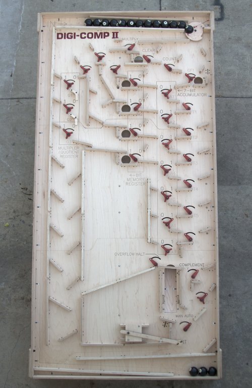

Hobby servo motors are the little wonders that make radio-control boats, airplanes, cars, hovercrafts, helicopters, submarines and robots work. And they are excellent devices for hacking.
Hobby servo motors each contain a little motor, which (through a set of gears) turns the output shaft, which is connected to a potentiometer, which provides position feedback to the controller chip inside the servo, which commands the motor to move until the output shaft reaches the desired position.
We’ve seen all kinds of crazy and wonderful servo modding– from the standard continuous rotation mod to the simple electronic speed controller, to full-on (servo) brain transplants.
Some time ago, I wrote up an article an article in Make Magazine, about how to modify a hobby servo motor to precisely control a one-ton scissor jack. The resulting sub-$100, one-ton linear servo motor can be used for any number of CNC and robotics projects. (For our own use, this was the Z-axis lift motor of the CandyFab 4000.)
We are now pleased to report that this project has just been released to the public over at Make Projects, where they have released a step-by-step version of the magazine article. (So go take a look!) One note: be sure to download the two PDF documents listed under “Files” — you’ll need those diagrams to follow along with the project.

Earlier this spring, we released our open-source ISP Shield for Arduino. After using them for a while, we’ve found a few ways to improve the design, so today we’re releasing version 2.0.


The ISP Shield 2.0 is also our first printed circuit board to feature the OSHW logo— the first of many, we hope. :)
The ISP shield kit is available at Evil Mad Science, and complete documentation is available at the Evil Mad Science Wiki.
A guest project by Dan Newman, contributing Evil Mad Scientist.

For my Eggbot plotting, I’ve had two seemingly exclusive goals: to execute
designs with food safe inks, and to use pens capable of producing fine, crisp
lines. Now, thanks to Lenore’s recent investigation of food safe markers combined with a simple five minute pen modification, it’s possible to achieve both goals with the same pen. Yes, I can have my eggs and eat them too!
Continue reading How to make precision fine line edible ink pens

We’ve just posted over 150 photos from this year’s Bay Area Maker Faire, in this here flickr set. What a blast!
(Above, Steve Hoefer demonstrates his Secret Knock Gumball Machine.)