What’s cooler than itty bitty alphanumeric LED displays? Freaking huge ultrabright alphanumeric LED displays, that’s what!
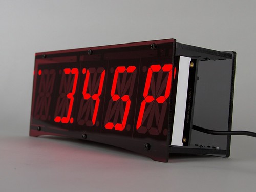
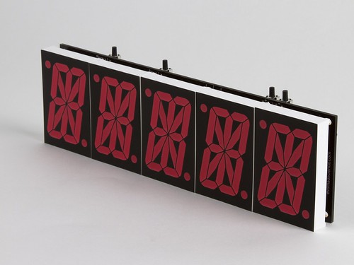
And so today we’re releasing a new kit, the Alpha Clock Five, an open-source, hacker-friendly alarm clock kit, based around an block of fiveultrabright red 2.3″ character height alphanumeric displays:
So, how big are these things?
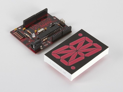
For scale, here’s one of the displays next to a Diavolino board:
These displays are great in many ways– they’re extremely bright for one –but the downside is that they are actually a bit tricky to drive. The 10 “big” segments each have two LED elements in series, twice in parallel, while the smaller segments have two LED elements in series, but not in parallel, and the decimal points each have a single LED element. To drive each LED element at (for example) 25 mA and 2 V requires 4V, 50 mA to be provided to ten segments, 4V 25 mA to the six short segments, and 2 V at 25 mA to each decimal point. And, it’s a fair number of signals to manage as well.
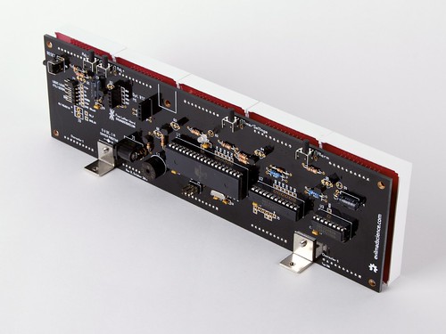
To solve the problem, we designed a multiplexed driver board, with two LED driver chips at different current set points. A 16-bit constant-current LED driver is preset at 50 mA and drives the ten large segments, while a separate 8-bit constant-current LED is preset at 25 mA and drives the short segments and the decimal place. The multiplexing is in analogy with an LED matrix, where each alphanumeric character comprises one row of our matrix– which just happens to have 54 LED elements inside. One row is switched on at a time by one of five transistors. We used high-current, low-saturation-voltage PNP transistors, type 2STX2220– the low saturation voltage means that you *can* use these to switch a useful 4 V load, even when running at 5 V.
The circuit board is 9.430 X 2.736″ in size, and extra stiff at 0.094″ thick in order to support those heavy LED displays in their sockets. An ATmega644A microcontroller runs the show, and is preloaded with a bootloader so that you can program it like a Sanguinoboard, through a version of the Arduino IDE with added extensions. There’s also a magnetic buzzer so that it can be a full-on alarm clock, and a spot for a Chronodot module, for good timekeeping and battery backup.
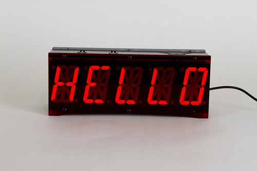
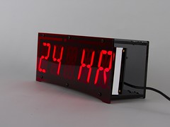
Here’s what the front of the “brick” looks like, with the five displays socketed next to one another. There are four right-angle tactile button switches hanging off of the top edge, so that you can adjust the time, alarm time, brightness, and so forth. If you hold the two rightmost buttons for a couple of seconds, it brings you to the options menu, where you can (for example) switch between 12 and 24 hour modes:

The circuit board, laden with alphanumeric displays, sits inside an acrylic case:
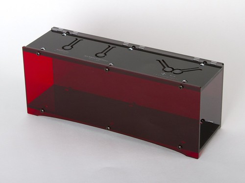
The front side of the case is deep red transparent acrylic (#2423 red transparent, should that come in handy), and serves to increase the contrast of the displays. The back of the case is gray transparent acrylic, and the top and bottom are black. The top surface has engraved labels for the four buttons, and four button keys cut into the acrylic. The thin beam flexes easily, contacting the right-angle switch below, when the circuit board is there.
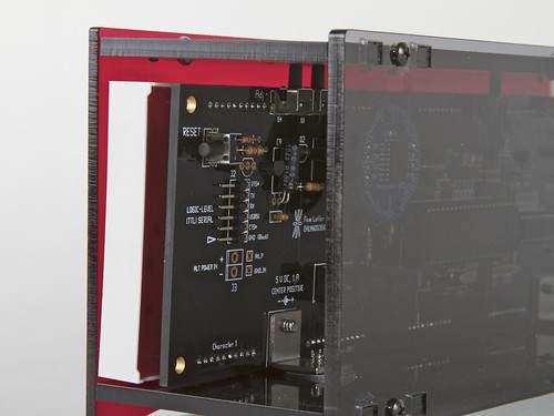
The back of the case is transparent so that you can see the circuit board. There’s also a white LED “night light” on the circuit board that can be enabled or disabled with the top buttons, and the sides are open to provide easy access to the TTL serial interface.
Obviously there’s a lot that could be done by hooking up a nice 5-character alphanumeric data display device to your computer.
On top of everything else, Alpha Clock Five is also a full-fledged alarm clock, right down to the snooze mode— although the word “SNOOZE” didn’t quite fit on the display (it says “SNOOZ,” if you must know).
Perhaps the biggest challenge for making it “bedroom compatible” was that it needed to not just be able to be extremely bright, it also has to be able to go crazy dim– which it can do, with fourteen levels of adjustable brightness.
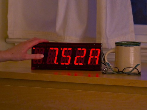
And it has some fantastic features as an alarm clock– for example multiple alarm tones and digits that are big enough to see even if you normally wear glasses.
And with a bit of code, it can be so much more. Soon, yours might say spell out “TRACY WAKE THE HECK UP” or use a couple of its spare I/O lines– and only make you coffee if you actually manage to get up on time.
Alpha Clock Five is available now at the Evil Mad Scientist Shop.


 Phillip at
  Nick over at
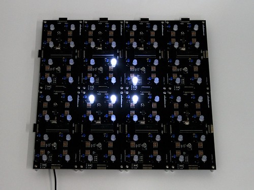
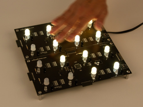
  Another ceiling mounted Peggy 2 installation was recently posted on the
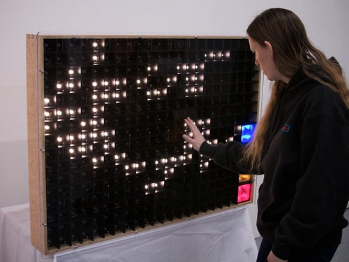
  Also at a museum in Pittsburgh, Deren Guler used a Peggy 2 in a kid-powered generator exhibit at the